52833 DK seemingly has backwards LED configuration

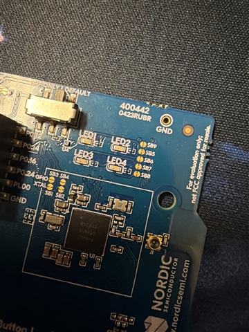
Hello, I have a particularly weird problem that I can't figure out how to solve. I was using the 52833 DK for software development and the onboard leds were blinking perfectly fine, but after a short break they don't seem to work at all. My previous code using the led api does nothing, the blinky example using GPIO api does nothing, and the developer academy lesson 1 and 2 don't do anything. But the LED definitely works. With a multimeter I can confirm that there is a voltage increase at the pins when the LED is driven, the diode test shows it working and if I bridge the right pad of LED1 with SB9 the LED will light up properly. The only conclusion I can come to is either that a software change made a difference in how the LEDs were drive or that the drive polarity in hardware somehow changed. I'm really at a loss for this one.

SDK version: v3.2.1

Board: nRF52833-DK

Code to reproduce:

#include <zephyr/kernel.h>
#include <zephyr/device.h>
#include <zephyr/devicetree.h>
#include <zephyr/drivers/gpio.h>

/* STEP 7 - Change the sleep time from 1000 ms to 100 ms */
#define SLEEP_TIME_MS 1000


/* LED0_NODE is the devicetree node identifier for the "led0" alias. */
#define LED0_NODE DT_ALIAS(led0)
static const struct gpio_dt_spec led = GPIO_DT_SPEC_GET(LED0_NODE, gpios);

int main(void)
{
    int ret;

    if (!device_is_ready(led.port))
    {
        return -1;
    }

    ret = gpio_pin_configure_dt(&led, GPIO_OUTPUT_ACTIVE);
    if (ret < 0)
    {
        return -1;
    }


    bool val = true;

    while (1)
    {
        val = !val;
        /* STEP 6.1 - Read the status of the button and store it */
        // bool val = gpio_pin_get_dt(&button);
        /* STEP 6.2 - Update the LED to the status of the button */
        gpio_pin_set_dt(&led, val);
        printk("Setting LED to to: %d!\n", val);

        k_msleep(SLEEP_TIME_MS); // Put the main thread to sleep for 100ms for power
                                 // optimization
    }
}
Parents
  • Those solder brides next to the LEDs look like they got cut, but pic quality is not good enough to be sure.

    Check those brides for connectivity - a cut bridge won't be able to lit the LED. Factory new board should have those bridges connected with a thin copper trace.

    Used board may have those cut when a dev needed some extra port pins for something else.

Reply
  • Those solder brides next to the LEDs look like they got cut, but pic quality is not good enough to be sure.

    Check those brides for connectivity - a cut bridge won't be able to lit the LED. Factory new board should have those bridges connected with a thin copper trace.

    Used board may have those cut when a dev needed some extra port pins for something else.

Children
No Data
Related