nRF52840 dongle BLE/ZigBee radio problem

I have recently purchased nRF52840 dongle which I wanted to use as a ZigBee sniffer. I bought it on AliExpress and it supposed to be original Nordic board, but it turned out to be a copy made in China. After programming it with Sniffer firmware I saw that no packets are received - the led is flashing that it is in packet capturing mode.

Then I tried to compile (with a difficulty) some BLE sample programs included in SDK to see whether BLE is working, but it doesn't work as well. 

My assumption is that the radio peripheral is not working. I am not sure how else I could check the radio. I have never used nRF products before.

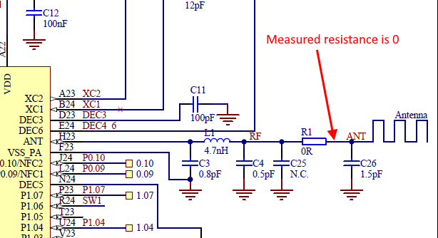
I had a look at the dongle board and there is one thing that I am not sure of. I measured resistance between R0 (antenna input) and the ground - see the picture below. The resistance is 0 Ohms. Since there are only capacitors that are connected to the ground from the antenna to the IC pin, I don't know why the resistance is 0.  Unless there is something internal (inductor) inside that chip that would create this value.

Could anyone advise what resistance should I expect at this point? If 0 Ohms resistance is correct what else can be the problem with the radio?

I would appreciate any help.

  • After more testing I don't think it is board (antenna connection) problem

    After spending more time when trying to use sample peripheral_lbs I found out that application fails on call to 

        err = bt_enable(NULL);
        if (err) {
            return 0;
        }

    it doesn't get to "if (err)" but reboots somewhere in the function bt_eanble().

    Any suggestions what can be wrong? I don't have any debugger so I can't do anything else.

  • Hi,


    There is an inductor internally, connected to ground, so measuring 0 ohm (or close to), is expected on the ANT pin.


    Can you try setting this, which enables internal 32k RC oscillator?

    CONFIG_CLOCK_CONTROL_NRF_K32SRC_RC=y


    This is usually the main reason why custom designs will not fully boot up, along with missing DCDC inductors in the design.

    However, since you are able to debug; it means that dcdc components are highly likely in place in your design.


    still have issues? Please share the link/schematic of the dongle.


    Kind regards,

    Håkon

  • Hello Håkon,

    Thank you for your response.

    I have tried your suggestion (again). I saw this suggestion on the internet before. Unfortunately the problem is still there.

    When you said "custom design", I know it is not original Nordic board but it is built on the same pcb layout and schematic as information provided with the original dongle.

    My debugging options are very limited. The only way I could do it is to put the line below before the call to bt_enable():

    dk_set_led(USER_LED, 1);

    And this led and another led are flashing fast. I don't know what sets this other led though. Thatt's why I believe MCU is rebooting.

    When I comment out everything from the call to bt_enable()  up to the "for" loop, this led is on and RUN_STATUS_LED is flashing slowly.

  • And I had a look at the board and it has X2 (32kHz) crystal.

  • Can you please share a schematic, link or similar related to the board itself?

    A picture of the dongle, both front + back, will help.


    Kind regards,

    Håkon

Related