Hi:
use nrf54l15 and ncs v3.1.1.
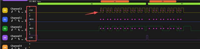
The CS-PIN remained low during measurement.
I am unable to control CS PIN through DPPI.
Here is the source code:
Hi:
use nrf54l15 and ncs v3.1.1.
The CS-PIN remained low during measurement.
I am unable to control CS PIN through DPPI.
Here is the source code: