This post is older than 2 years and might not be relevant anymore
More Info: Consider searching for newer posts

PTR5518 IO pins

Hi

I'm very new and looking at the PTR5518 breakout board. The docs below specify some of the pins:

image description image description

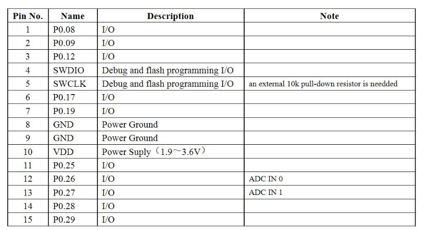
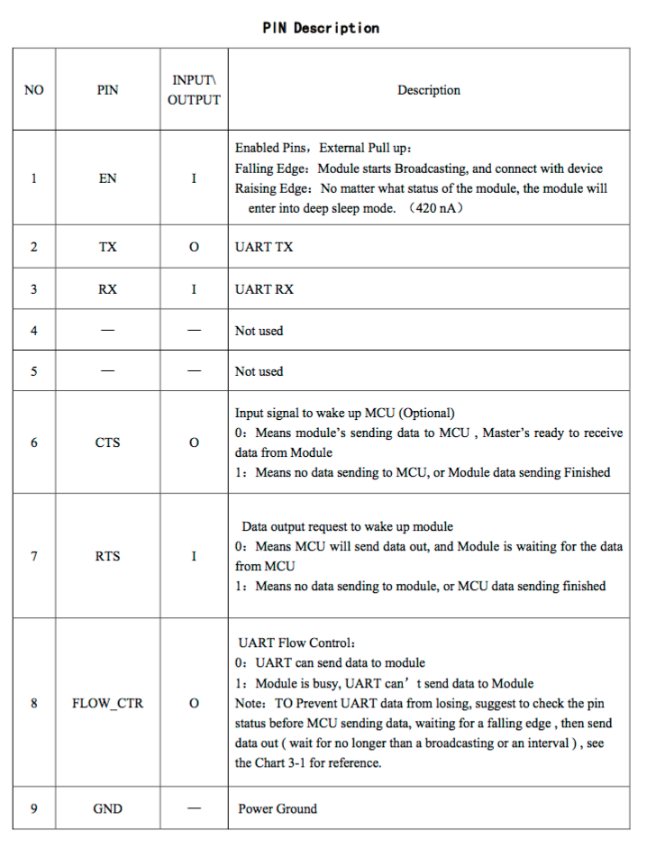
Are the pins EN, RX, TX, RTS etc. tied to P0.08, P0.09, P0.12, P0.19, respectively, only in the stock firmware? That is, these pins are tied to EN, RX, RTS, etc. because that's how they're defined in the firmware. So, a custom firmware could well give very different pin assignments. But then, isn't it necessary to ground EN in order to ground RTS (P0.19) in order to program the board? If so, is it that P0.19 needs to be grounded for flash programming?

Thanks

  • Hi

    You can use SWDIO and SWDCLK for programming so no need to worry about the RTS and EN pins. Normally RTS and CTS is UART flowcontrol pins, but in this case I am not sure since the module has a separate FLOW_CTR pin. Does the datasheet say anything about what the RTS and CTS pins are used for?

    From my understanding EN is equal to NO1 which is equal to P0.08. All digital functions on the nRF51 can be assigned to any pin, only analog functions (ADC, LPCOMP) needs specific pins (AIN0-AIN7).

Related