
Hi Nordic team,
I have an issue with SPI slave timing on nRF54H20 after I change to a new partitioning scheme that mimics the single-slot DFU / merged-slot layout, even though MCUboot / firmware loader are not enabled yet. With the default partitioning everything works fine, but with the new partitioning the SPIS read is delayed when BLE notifications are enabled.
Hardware / SDK
- nRF54H20 DK (BLE peripheral + SPIS)
- nRF52840 (SPI master, SPIM)
- PC as BLE central
- NCS version: v3.3.0
System description
- nRF52840 (SPIM master) → SPI data → nRF54H20 (SPIS, BLE peripheral) → BLE notifications → PC (central).
- SPI traffic: 256 packets/second, each ~60 bytes.
- nRF54H20 SPIS thread:
- Reads SPI data from master.
- Packs data into BLE notifications.
- Sends notifications to PC.
Project structure / partitioning
- I use a common memory map file:
sysbuild/nrf54h20dk_nrf54h20_memory_map.dtsi. - This file is included by:
boards/nrf54h20dk_nrf54h20_cpuapp.overlaysysbuild/uicr.overlaysysbuild/ipc_radio/boards/nrf54h20dk_nrf54h20_cpurad.overlay
- When the file
sysbuild/nrf54h20dk_nrf54h20_memory_map.dtsiis empty (all content commented out), the build uses the default partitioning and everything works (no SPI delay). - When I enable the custom content in
nrf54h20dk_nrf54h20_memory_map.dtsi(merged-slot / single_slot-like layout), the SPI delay appears when BLE notifications are enabled.
This is the only change between the “working” and “problem” builds.
/*
 * Copyright (c) 2025 Nordic Semiconductor ASA
 *
 * SPDX-License-Identifier: LicenseRef-Nordic-5-Clause
 */

/* On nRF54H20 the FW loader mode is supported in the merged slot configuration
 * Extend slot0_partition and slot1_partition to cover both application and
 * radio images, as well as MCUboot image metadata (header and trailer).
 * Those partitions will be used by MCUboot to verify the merged image to boot.
 * Apart from that, they will be used by the MCUmgr subsystem to correctly
 * handle flags, stored inside the MCUboot image trailer.
 * Use cpu<app|rad>_slot<0|1>_partition as zephyr,code-partition, so the
 * application and radio sizes are correctly reported.
 */
/delete-node/ &cpuapp_slot0_partition;
/delete-node/ &cpuapp_slot1_partition;
/delete-node/ &cpurad_slot0_partition;
/delete-node/ &cpurad_slot1_partition;

/delete-node/ &cpuppr_code_partition;
/delete-node/ &cpuflpr_code_partition;

/*
 * Secondary boot is not used by this sample, as it has a somewhat
 * similar functionality as firmware loader.
 * Hence, we remove the secondary boot partitions and push the
 * storage_partition and periphconf_partition further back to the freed
 * space.
 */
/delete-node/ &secondary_partition;
/delete-node/ &secondary_periphconf_partition;
/delete-node/ &storage_partition;
/delete-node/ &periphconf_partition;

/* Remove the undefined property value from the disabled VPR cores to prevent build errors. */
&cpuflpr_vpr {
	    /delete-property/ source-memory;
};

&cpuppr_vpr {
	    /delete-property/ source-memory;
};

&mram1x {
	    partitions {
		        /* Main application with the MCUboot header. */
		        slot0_partition: partition@30000 {
			            reg = <0x30000 DT_SIZE_K(1612)>;
		        };

		        /* Application code partition. */
		        cpuapp_slot0_partition: partition@30000 {
			            reg = <0x30000 DT_SIZE_K(1354)>;
		        };

		        /* Radio code partition. */
		        cpurad_slot0_partition: partition@182800 {
			            reg = <0x182800 DT_SIZE_K(256)>;
		        };


		        /* Merged partition used by the FW loader. */
		        slot1_partition: partition@1cc000 {
			            reg = <0x1cc000 DT_SIZE_K(144)>;
		        };

		        /* Application code partition (part of the FW loader).
		         * Offset by the MCUboot header size (2048 bytes).
		         */
		        fw_loader_partition: cpuapp_slot1_partition: partition@1cc800 {
			            reg = <0x1cc800 DT_SIZE_K(60)>;
		        };

		        /* Radio code partition (part of the FW loader). */
		        cpurad_slot1_partition: partition@1db800 {
			            reg = <0x1db800 DT_SIZE_K(82)>;
		        };

		        boot_request: partition@1f0000 {
			            reg = <0x1f0000 16>;
		        };

		        boot_request_backup: partition@1f0010 {
			            reg = <0x1f0010 16>;
		        };

		        storage_partition: partition@1f1000 {
			            reg = <0x1f1000 DT_SIZE_K(40)>;
		        };

		        periphconf_partition: partition@1fb000 {
			            reg = <0x1fb000 DT_SIZE_K(8)>;
		        };
	    };
};
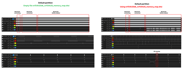
How I detect the SPI delay (logic analyzer + test points)
The attached logic analyzer screenshot was captured with the following instrumentation around the SPIS spi_transceive() call:
On the logic analyzer:
- TP3 shows when the SPIS driver is inside
spi_transceive(). - TP0 shows the post‑processing of the received SPI frame.
- TP1 is only asserted when the 16‑bit counter in the payload is not consecutive, indicating that a frame was delayed or lost.
After switching to the new partitioning scheme (aligned with single‑slot DFU) but with MCUboot still disabled, the TP3 window becomes noticeably longer between the master asserting CS/SCK and the SPIS transaction completing, which matches the observed read delay on nRF54H20.
static int spi_slave_poll(void)
{
...
    test_point_set_tp3();
    rv = spi_transceive(spi_slave_dev, &spi_slave_cfg, &s_tx, &s_rx);
    test_point_clear_tp3();

    test_point_set_tp0();
    if (rv) {
        _counter = (uint16_t)((spis_rx_buffer[5] << 8) | spis_rx_buffer[4]);
        if (_counter != (uint16_t)(pre_counter + 1)) {
            test_point_set_tp1();
            test_point_clear_tp1();
        }
        pre_counter = _counter;
    }
    test_point_clear_tp0();
    return 0;
}
Questions:
1. Can you please review my nrf54h20dk_nrf54h20_memory_map.dtsi and the related overlay files to check if there is any mistake in: MRAM partition definitions (offsets, sizes, gaps)
2. How the common memory map is included for each image (application core, radio core, bootloader)?
3. Is there anything specific in the new nRF54H20 memory map / merged-slot configuration that could affect SPIS timing or performance, even when MCUboot is not enabled?
I am happy to provide a minimal project that reproduces the issue if needed (private ticket)
Thanks,