nRF9151 NTN COEX2 + MAGPIO inconsistent timing

Hi,

We're testing NTN functionality with the nRF9151 and have noticed something weird with the timings of MAGPIO and COEX2. We use COEX2 to control the power domain for our RF front end, and have the following settings

AT%SHORTSWVER
%SHORTSWVER: nrf9151-ntn_1.0.1

AT%XCOEX2?
%XCOEX2: 1

AT%XMAGPIO?
%XMAGPIO: 1,1,0,3,2,690,1562,1,1563,1587,2,1588,2200

For testing I've just used large frequency ranges in MAGPIO, but that shouldn't matter.

Then, to test the timing I've been using

AT%XRFTEST=0,1,255,15379,-80,0

to trigger the RF. This all works and I see the pins toggle, but the timing seems wrong.

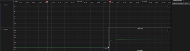
For the very first activity in a boot, we get COEX2 going ~1ms before MAGPIO, which is what I expect
However, for ALL subsequent events, MAGPIO goes BEFORE COEX2, and the timing of how long before COEX2 can be controlled by the COEX2 anticipation.
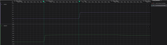
The above image is with COEX2=1, but if we reduce this (COEX2=3) then we get the following
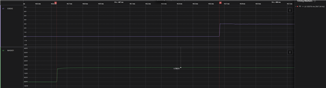
Is this expected behaviour? 

Parents
  • Hi,

    Thanks for the detailed report and captures. I got a explanation and confirmation from the R&D that this behavior is expected and here's the explanation.

    You're right that COEX2 is behaving correctly and as documented. The part that looks odd is MAGPIO, and it comes down to how its pin state is handled. A MAGPIO pin needs two things to actually go high, it has to be told to go high (an internal OUT register set to 1), and it has to have power (an LDO that's only on while the RF domain is on).

    • On the first RF activity after boot, MAGPIO has never been programmed (OUT = 0). When you start RF, the pin gets power immediately, but MAGPIO is only set to 1 later at the moment RF actually starts RX. That later step is the ~1 ms difference, so MAGPIO rises after COEX2, as you expect.
    • When you stop RF (XRFTEST=0,0), MAGPIO's OUT is not cleared, it stays at 1 but the RF/LDO power is removed, so the pin voltage drops to 0.
    • Then when you send the next XRFTEST command, the OUT register already still is ‘1'. The reason you then see the MAGPIO going ‘1’ earlier than expected, is because it happens at the moment when the LDO is powered up. That happens a bit earlier than the COEX2 rise. It’s not very well documented, i give you that. MAGPIO is intended mainly for antenna tuning, so we guarantee its state being right when RF is enabled and frequency is as configured, but not otherwise. You can also configure state ‘0’ to MAGPIO and we didn’t want to make assumptions about what should be the state in off.

    So the seen behavior is expected, but agreeably a bit confusing. If you want a reference for the RF start that doesn’t suffer from this, please configure COEX0 pin instead of MAGPIO (using AT%XCOEX0).

    Then you might wonder why don’t the COEX0 and COEX2 pins have the same behavior. The reason is that the COEX pin state, including the OUT, is reset when RF is powered down with XRFTEST=0,0. So they always start with OUT='0'. But MAGPIO is a “modem-application” GPIO, whose state is not reset at RF domain power-down, only the LDO powering is removed.

    One extra note that there's a special case for GPS / band 24, where XRFTEST=0,0 does clear MAGPIO's OUT back to 0. Like if you give command AT%XRFTEST=0,1,24,15750,-80,0 (24 = GPS band, and 1575 MHz). Therefore with the next XRFTEST you should not see the swapping of order if MAGPIO and COEX2. To confirm we are talking about the same thing:

    <boot>
    
    AT%XMAGPIO=<your config>
    
    AT%XRFTEST=0,1,255,15379,-80,0   (MAGPIO and COEX2 order as expected)
    
    AT%XRFTEST=0,0
    
    AT%XRFTEST=0,1,24,15750,-80,0  (the GPS RX) 
    
    AT%XRFTEST=0,0 (this now clears MAGPIO OUT register)
    
    AT%XRFTEST=0,1,255,15379,-80,0   (MAGPIO and COEX2 order still as expected).

    So in short COEX2 is fine, the MAGPIO ordering is expected (its last state isn't cleared between RF sessions), and COEX0 is the recommended pin if you want a reliable RF-start reference. I hope it helps.

    Best Regards,
    Syed Maysum

Reply
  • Hi,

    Thanks for the detailed report and captures. I got a explanation and confirmation from the R&D that this behavior is expected and here's the explanation.

    You're right that COEX2 is behaving correctly and as documented. The part that looks odd is MAGPIO, and it comes down to how its pin state is handled. A MAGPIO pin needs two things to actually go high, it has to be told to go high (an internal OUT register set to 1), and it has to have power (an LDO that's only on while the RF domain is on).

    • On the first RF activity after boot, MAGPIO has never been programmed (OUT = 0). When you start RF, the pin gets power immediately, but MAGPIO is only set to 1 later at the moment RF actually starts RX. That later step is the ~1 ms difference, so MAGPIO rises after COEX2, as you expect.
    • When you stop RF (XRFTEST=0,0), MAGPIO's OUT is not cleared, it stays at 1 but the RF/LDO power is removed, so the pin voltage drops to 0.
    • Then when you send the next XRFTEST command, the OUT register already still is ‘1'. The reason you then see the MAGPIO going ‘1’ earlier than expected, is because it happens at the moment when the LDO is powered up. That happens a bit earlier than the COEX2 rise. It’s not very well documented, i give you that. MAGPIO is intended mainly for antenna tuning, so we guarantee its state being right when RF is enabled and frequency is as configured, but not otherwise. You can also configure state ‘0’ to MAGPIO and we didn’t want to make assumptions about what should be the state in off.

    So the seen behavior is expected, but agreeably a bit confusing. If you want a reference for the RF start that doesn’t suffer from this, please configure COEX0 pin instead of MAGPIO (using AT%XCOEX0).

    Then you might wonder why don’t the COEX0 and COEX2 pins have the same behavior. The reason is that the COEX pin state, including the OUT, is reset when RF is powered down with XRFTEST=0,0. So they always start with OUT='0'. But MAGPIO is a “modem-application” GPIO, whose state is not reset at RF domain power-down, only the LDO powering is removed.

    One extra note that there's a special case for GPS / band 24, where XRFTEST=0,0 does clear MAGPIO's OUT back to 0. Like if you give command AT%XRFTEST=0,1,24,15750,-80,0 (24 = GPS band, and 1575 MHz). Therefore with the next XRFTEST you should not see the swapping of order if MAGPIO and COEX2. To confirm we are talking about the same thing:

    <boot>
    
    AT%XMAGPIO=<your config>
    
    AT%XRFTEST=0,1,255,15379,-80,0   (MAGPIO and COEX2 order as expected)
    
    AT%XRFTEST=0,0
    
    AT%XRFTEST=0,1,24,15750,-80,0  (the GPS RX) 
    
    AT%XRFTEST=0,0 (this now clears MAGPIO OUT register)
    
    AT%XRFTEST=0,1,255,15379,-80,0   (MAGPIO and COEX2 order still as expected).

    So in short COEX2 is fine, the MAGPIO ordering is expected (its last state isn't cleared between RF sessions), and COEX0 is the recommended pin if you want a reliable RF-start reference. I hope it helps.

    Best Regards,
    Syed Maysum

Children
No Data
Related