nPM2100 EK single cell AAA - IBALIM

Hello,

We use the nPM2100 EK for getting familiar with nPM2100 for its potential use in our project where we aim to use single AAA battery for powering it.

Our usage profile is simulated in the measurement attached below, where:

  • top chart represents output voltage ~3.3V and input voltage (AAA battery)
  • middle chart represents current drawn from the battery
  • bottom chart represents an approximated AAA battery internal resistance (rough estimate - it shouldn't be compared to standard DS values)

Long story short, the battery is periodically loaded with ~50mA @ VOUT (~3.3V) - 1minute ON, 1 minute OFF. During the ON state, in the middle, the load is increased (for 5s) to ~100mA @ VOUT (~3.3V) which is the maximum we expect to draw from the battery.

We test when the output voltage drops below the desired 3.3V level which happens at the end of the measurement. At this state, the output voltage drops and the battery current increases.

Question:

Could you advise why the measured battery current saturates ~600mA when we have the IBALIM set to 800mA?

IMHO:

  • In case the bottleneck was the battery, its voltage would drop further, right? It doesn't do that.
  • The inductor selected inside the EK seems to have good saturation current rating.

We also used the default config of 600mA, the measured values were lower ~540mA.

Our measurement is performed with INA228 with 0.1Ohm shunt resistor, ~1 sample/second. It's quite under sampled. On the other hand, since IBATLIM is "Battery (valley) current limit setting", I believe the 800mA we set is actually the threshold when the ON state is re-activated again (the inductor gets charged again). So the average value would be higher than this level BUT it's lower...

Thank you!

  • Hi Jiri, 

    Currently we are facing a short wait until another team member returns to the office. I will give a follow up here when they return next week.

    Jiri B. said:
    I'm not sure what the "boost output rating of 150mA" means exactly.

    Poor wording on my end. I was only referring to the maximum value for the boost output.

    Best regards,

    Maria

  • Hi Maria,

    Thank you. Let me know as soon as you have new input.

    At our end, we repeated the tests using a laboratory power supply instead of a battery, to rule out battery ESR/current-limiting as a factor (the PSU's current limit was set well above 1.5A throughout, so it was never the constraint). Two main results:

    1. Maximum IBAT reached: ~720 mA (BOOST @ 3.3V into 20Ω, LDO @ 3.0V into 60Ω). This occurred as VBAT was lowered to ~1.0–1.1V, at which point VOUT had already dropped significantly below its 3.3V target — to 2.5V and below. So the ~720mA figure is not a stable, in-regulation operating point; it's the current drawn right as the boost is losing regulation.
    2. We could not reach IBATLIM=800mA with this loading. Instead, we found a genuine steady state at VBAT=1.44V, IBAT=670mA, where VOUT settled at 3.07V (already ~7% below the 3.3V target rather than fully regulating). As we lowered VBAT further from there, VOUT continued dropping — down to roughly 2.2–2.3V — while IBAT only rose to the ~720mA peak noted above; it never approached 800mA.

    One difference worth flagging versus our earlier battery-based tests: those used BOOST @ 3.3V into 33Ω only (no LDO load), whereas this round used 20Ω on BOOST plus 60Ω on the LDO. So the two data sets aren't directly comparable on load — but in both cases we've been unable to get anywhere near 800mA while VOUT stays in regulation.

    Our question: under what conditions is it actually possible to reach IBAT close to the 800mA IBATLIM ceiling?

    So far it seams that in our original question, the limitation wasn't realized by the IBATLIM protection but rather by nPM efficiency.

    Best regards,
    Jiri

  • Hi Jiri, 

    The feedback I got was that we also see saturation before reaching the IBATLIM on higher settings. Inaccuracies and variation are to be expected for the higher settings. For example, our test with 0.9V VBAT 600mA IBATLIM had a DC limit of 570mA while the 800mA IBATLIM had a limit of 677mA. The specified maximum current limits are with VBAT >1.25V and if the VBAT drops below like in this case 1V the maximum current will be lower.

    Regarding your current question on how IBAT can get closer to IBATLIM. In the register description we include nominal values, so variations because of temperature, process and voltage variation is expected. 

    What is your main boost converter load value for your application? At that value, is there a risk of hitting the batttery current limit? Also, could you please provide the values for the maximum load, output voltage and minimum input voltage? When we have that information, the team can look for internal data on similar configurations. 

    Best regards,

    Maria

  • Hi Maria,

    thanks for coming back. Please, excuse my late reply - holiday.

    The feedback I got was that we also see saturation before reaching the IBATLIM on higher settings. Inaccuracies and variation are to be expected for the higher settings. For example, our test with 0.9V VBAT 600mA IBATLIM had a DC limit of 570mA while the 800mA IBATLIM had a limit of 677mA. The specified maximum current limits are with VBAT >1.25V and if the VBAT drops below like in this case 1V the maximum current will be lower.

    Understood.

    Regarding your current question on how IBAT can get closer to IBATLIM. In the register description we include nominal values, so variations because of temperature, process and voltage variation is expected. 

    Understood.

    What is your main boost converter load value for your application? At that value, is there a risk of hitting the batttery current limit?

    We expect 100mA @ 3.3V (it's expected to happen a few times during the battery life cycle = ~1year; the load will increase from ~50mA to 100mA for ~5s, then it will decrease to 50mA).

    We have been working on consumption measurements to confirm this target. Still, work in progress.

    The risk of hitting IBATLIM changes throughout the battery life cycle. As the battery gets discharged, its parameters (OCV, ESR, etc.) change until a point when the whole power source becomes unreliable (can't deliver the power AND/OR VOUT can't be reached, etc.). It's described in my original post (++ details clarified in the later ones) with the charts attached. As the battery OCV decreases and the ESR increases, the nPM efficiency decreases => IBAT increases => efficiency drops => IBAT increases... Moreover, the higher IBAT => CCV decreases => IBAT increases => CCV decreases... The positive feedback already described above. 

    It's an optimization problem where we try to maximize the battery lifetime (it's useful capacity) while making sure the power source remains reliable (e.g. it can deliver the power, VOUT doesn't drop below the allowed threshold - NOT SPECIFIED yet, etc.).

    Also, could you please provide the values for the maximum load, output voltage and minimum input voltage?

    The maximum load: 100mA @ 3.3V.

    VOUT = 3.3V. It must not drop below 3.1V - STILL UNDER CLARIFICATION.

    Minimum VBAT is hard to tell. As stated above - we try to maximize the battery useful capacity. We also don't want the battery to leak into the device. From our trials, it looks VBAT can go down to ~0.91V while the VOUT doesn't go below ~3.1V (i.e. battery OCV ~1.25V, battery ESR ~0.62Ω, battery CCV ~0.91V with 100mA at VOUT). 

    You might actually be able to help us. As I understand, in order to implement the Fuel Gauge, Nordic performed characterization of many alkaline batteries. That means Nordic must have a huge data set at its disposal. Based on VOUT (=3.1V) and IOUT (=100mA), what minimum VBAT can be used?

    Out of that, we could derive battery CCV and out of that OCV and ESR. 

    We can connect directly/privately if better.

    Thank you!

    Best regards,

    Jiri

  • Hi

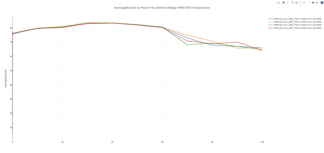
    Here's the characterization results we have with 0.9V input voltage and 3.3V output voltage (load sweep up to 100mA). Efficiency on Y axis, load on X axis:

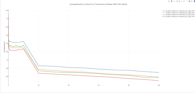
    Load regulation. Output voltage on Y axis, Load on X axis:

    I hope these will be useful for you.

    Best regards,

    Simon

Related