FEM issue

Our device is using NRF54L15 for BLE function.
When we test the max distance of ble connection between 2 devices, we get the below results.

We are confused by these results.
Shall not the result with FEM and higher Tx power be better than the one without FEM and lower Tx power.
Do you have any idea about what is the potential cause for these results.

Parents
  • Thank you for the update, and my apologies for the late reply.

    After deep diving into the RFX2401C datasheet, no clear improvement after changing ctx-settle-time-us and crx-settle-time-us to 23 µs / 5 µs seems to be not helpfull for your type of measurements, however it should be still valid or corrected by you for fine tuning in such a setup: RFX2401C + SoC radio rampup.

    I think the more likely issue is tx-gain-db configuration and how MPSL splits TX power on simple GPIO FEM.

    For simple GPIO FEM, tx-gain-db must match real PA gain at your operating point. SKY66112 defaults to 22 dB. RFX2401C is not in Nordic’s supported FEM table - gain must be validated on your hardware.

    For antenna power requests, the stack calls mpsl_fem_tx_power_split, returning mpsl_tx_power_split_t with RADIO.TXPOWER and FEM control via mpsl_fem_pa_power_control_set. Simple GPIO FEM has no built-in power model - MPSL uses fixed tx-gain-db from devicetree: radio_tx_power = requested − tx_gain_db 

    If you need other tx power map you can use custom compensation via mpsl_fem_power_model_set / fetch api - it is not provided for third-party FEMs.

    Real antenna power ≈ SoC tx power + actual PA gain - mind that outcome is not a simple arithmetic calculation if gain is wrong or SoC drive is outside the PA linear region of FEM.

    Example:

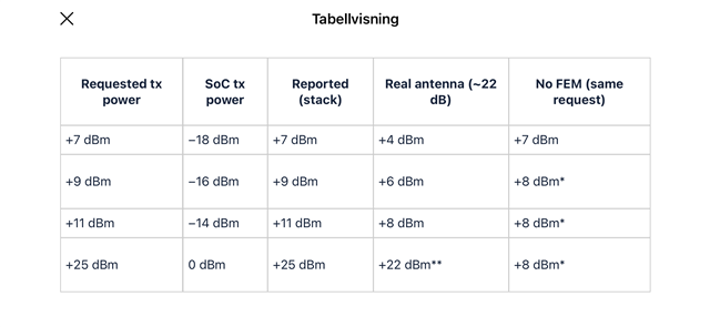
    FEM config tx-gain-db = 25, actual PA gain ≈ 22 dB:


    *No FEM set to max SoC +8 dBm (in nRF54L15 case).
    **RFX2401C saturated output max ~+22 dBm - stack reports +25 dBm but PA cannot deliver it.

    When requested antenna power equals tx-gain-db, SoC tx power is set to 0 dBm  - a sensible FEM operating point (moderate/default PA input). 

    With tx-gain-db = 22 and request +22 dBm, SoC = 0 dBm, reported +22 dBm, real antenna ≈ +22 dBm if gain is correct - aligned with RFX2401C max saturated output.


    Our recommendation:

    Operate at valid FEM power points — choose requested antenna power so SoC tx power stays in the PA’s linear region. When requested power = tx-gain-db, SoC = 0 dBm (e.g. tx-gain-db = 22 → request +22 dBm for RFX2401C max). Avoid high requested power with overstated gain that pushes SoC deep below 0 dBm (+11 dBm with tx-gain-db = 25 → −14 dBm SoC).

    Or apply a custom power model — if target power cannot align with a valid operating point, implement mpsl_fem_power_model_set with a fetch callback to control SoC/FEM split for non-linearity, saturation, and quantization on nRF54L. Nordic provides no built-in model for simple GPIO / third-party FEMs.

    Stine

Reply
  • Thank you for the update, and my apologies for the late reply.

    After deep diving into the RFX2401C datasheet, no clear improvement after changing ctx-settle-time-us and crx-settle-time-us to 23 µs / 5 µs seems to be not helpfull for your type of measurements, however it should be still valid or corrected by you for fine tuning in such a setup: RFX2401C + SoC radio rampup.

    I think the more likely issue is tx-gain-db configuration and how MPSL splits TX power on simple GPIO FEM.

    For simple GPIO FEM, tx-gain-db must match real PA gain at your operating point. SKY66112 defaults to 22 dB. RFX2401C is not in Nordic’s supported FEM table - gain must be validated on your hardware.

    For antenna power requests, the stack calls mpsl_fem_tx_power_split, returning mpsl_tx_power_split_t with RADIO.TXPOWER and FEM control via mpsl_fem_pa_power_control_set. Simple GPIO FEM has no built-in power model - MPSL uses fixed tx-gain-db from devicetree: radio_tx_power = requested − tx_gain_db 

    If you need other tx power map you can use custom compensation via mpsl_fem_power_model_set / fetch api - it is not provided for third-party FEMs.

    Real antenna power ≈ SoC tx power + actual PA gain - mind that outcome is not a simple arithmetic calculation if gain is wrong or SoC drive is outside the PA linear region of FEM.

    Example:

    FEM config tx-gain-db = 25, actual PA gain ≈ 22 dB:


    *No FEM set to max SoC +8 dBm (in nRF54L15 case).
    **RFX2401C saturated output max ~+22 dBm - stack reports +25 dBm but PA cannot deliver it.

    When requested antenna power equals tx-gain-db, SoC tx power is set to 0 dBm  - a sensible FEM operating point (moderate/default PA input). 

    With tx-gain-db = 22 and request +22 dBm, SoC = 0 dBm, reported +22 dBm, real antenna ≈ +22 dBm if gain is correct - aligned with RFX2401C max saturated output.


    Our recommendation:

    Operate at valid FEM power points — choose requested antenna power so SoC tx power stays in the PA’s linear region. When requested power = tx-gain-db, SoC = 0 dBm (e.g. tx-gain-db = 22 → request +22 dBm for RFX2401C max). Avoid high requested power with overstated gain that pushes SoC deep below 0 dBm (+11 dBm with tx-gain-db = 25 → −14 dBm SoC).

    Or apply a custom power model — if target power cannot align with a valid operating point, implement mpsl_fem_power_model_set with a fetch callback to control SoC/FEM split for non-linearity, saturation, and quantization on nRF54L. Nordic provides no built-in model for simple GPIO / third-party FEMs.

    Stine

Children
No Data
Related