Dear Experts,
We are bringing up a custom nRF54LS05B module and have built a small production-test
firmware on top of the `radio_test` sample. While characterising current
consumption, we ran into a behaviour we would like to understand, plus a couple
of smaller questions about the datasheet.
### What we added to the sample
We kept the sample's own shell commands and added a few `cansec_*` shell
commands for the production line. To call the radio functions from our own
command file we made `radio_rx()` and `radio_unmodulated_tx_carrier()`
externally visible (they are `static` in the stock `radio_test.c`).
Continuous wave (CW) test:
```c
static int cmd_bjja_lm_tx_test(const struct shell *shell, size_t argc, char **argv)
{
shell_print(shell, "[weli]CW start.\r\n");
/* mode 0 = NRF_RADIO_MODE_NRF_1MBIT, channel 40 -> 2440 MHz */
radio_unmodulated_tx_carrier(0, 4, 40); /* was (0, 8, 40)
}
```
RX test:
```c
static int cmd_bjja_lm_rx_test(const struct shell *shell, size_t argc, char **argv)
{
shell_print(shell, "[weli]RX start.\r\n");
/* last argument 0 = do not arm the RX timeout, stay in RX indefinitely */
radio_rx(0, 40, TRANSMIT_PATTERN_RANDOM, 0);
}
```
Additions to `prj.conf` on top of the stock sample's:
```
CONFIG_BT=y
CONFIG_PM_DEVICE=y
CONFIG_POWEROFF=y
```
We also add an application devicetree overlay that moves the UART to
`TX = P1.4`, `RX = P1.5` with no hardware flow control.
We are using a Fluke 17B+.
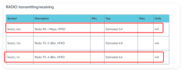
At TX CW, we measured a current of 7.85mA, and at RX, the current is 4.87mA.
Your datasheet states that TX CW at 4dBm should be 6.6mA, and RX current should be 3.4mA.
How can we make our module's current closer to these values?