Issues with External 32 MHz Crystal Oscillator Startup for nRF54Lm20A

Hello,
I am developing a mouse product using the nRF54LM20A (QFN52). Several prototype boards have been built and are currently under debugging. The hardware uses an external 32 MHz crystal with internal‑configured load capacitors.
I have observed that on some boards, the crystal fails to start oscillating when powered by battery only. However, once USB power is plugged in (USB power detection triggered), the crystal starts normally. After that, if the USB cable is unplugged and USB power is removed, the crystal keeps oscillating properly.
To summarize: the crystal cannot start up without USB power, but it can start normally when USB power is present. Could you please advise which configuration setting may be causing this behavior? Thank you!
Parents
  • Hi , 

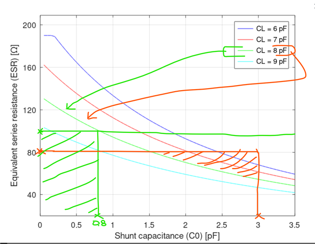
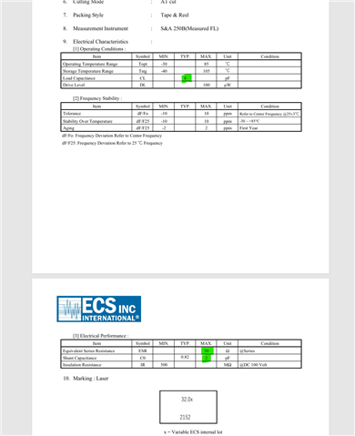
    There is a graph in nRF54LM20 datasheet for crystal selection, a good candidate for crystal is the one that the rectangle from ESR value and shunt capacitance (C0) falls well below C_ line. The crystals you used, one of them is having area above CL line that might cause issue if the crystal fall in that region. The other one does not provide C0 value in datasheet, so we cannot fully conclude on that. In below picture green and red lines are two crystals you shared:


    As as example below crystal would be a good candidate:
    ECS-320-CDX-2152


    Also please try to modify the USB VBUS pin path to make it similar to reference design to see if the issue persist or not. 

    Br,

    Ressa

  • Generally speaking, discrepancies between the actual crystal used and the required specifications will result in frequency deviation, but will not completely prevent the crystal from oscillating. Furthermore, the crystal oscillates normally under Vbus power input. Based on common reasoning, the root‑cause of the issue lies not in the crystal oscillation circuit, but in different configuration settings adopted by the firmware for the applied components.We have checked the VBUS path and found no particular discrepancy versus the reference design

  • Only parameter that can have big impact on oscillation of crystal is internal load caps. Let me know what caps values you have used in FW for the mentioned crystals. 

  • &hfxo {

    load-capacitors = "internal";

    load-capacitance-femtofarad = <8000>;

    };

  • We found that the boards with 32 M crystal failing to oscillate were running the Bluetooth example code. When the USB or 2.4 G example code is enabled, the crystal starts up normally.

  • This is not correct. You should follow below formula for setting the actual load caps on pins:

    C1=C2=2*CL-Cpin , Cpin can be assumed 3 pF, but it can vary depending on SoC and its package. 3pF is a good starting point. 

    So if the datasheet mentioning 8 pF:

    C1=C2=2*8 - 3 =13 pF . So you should set the load caps in FW to 13000 fF not 8000fF.
    Also in SW of you need to enable HFXO to be able to have crystal running. Just placing crystal does not mean it will start automatically and run all the time. 

  • Thanks for your info. I’ve tested various load capacitance configurations with no success. As you pointed out, the crystal is probably not properly started in the example code. How can we enable the crystal correctly in the SDK? Thanks.

Reply Children
  • Hi,

    Could explain how you are checking / debugging the crystal ? It is not recommended to directly probe the crystal pads as it will cause stability issue due to parasitic impedance that your probe will add to the nodes. 
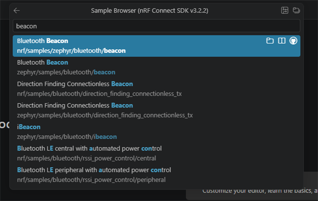
    One easy way is to use a SDK samples made for Bluetooth and then see if you are able to get stable connection. Below example is a good one that can be built without any modification for custom boards:


    If you want to debug in lower level. You can use radio test sample in SDK. You will need to have a UART connection to the SoC to send the commands. With that you can set the device in CW mode and check the accuracy of RF signal from antenna port. You will need to have a spectrum analyzer to check that. Also the frequency offset you see from RF signal will show you how accurate the load caps are. 


    HFCLK controller • nRF54LM20A | nRF54LM20B Datasheet • Technical Documentation


    Br,
    Ressa

Related