Nrf9151-DK with x_nucleo_wba25a1 shield (Zephyr, SPI/UART)

Hello,

I write to ask if there is a known problem with this combination of hardware.

  • Nrf9151-DK
  • x_nucleo_wba25a1

At this point, I just want to get the Zephyr example ./samples/bluetooth/periodic_adv_rsp running.

Recreate the problem:

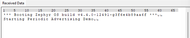
I get the following output: 

*** Booting Zephyr OS build v4.4.0-6649-gc74133ec989e ***

Starting Periodic Advertising Demo

[00:00:00.503,906] <err> bt_driver: IRQ pin did not raise

[00:00:00.503,936] <err> bt_driver: Error -5

[00:00:00.503,936] <err> bt_hci_core: Unable to send to driver (err -5)

[00:00:00.504,028] <wrn> bt_hci_core: opcode 0x1003 status 0x1f Bluetooth init failed (err -5)


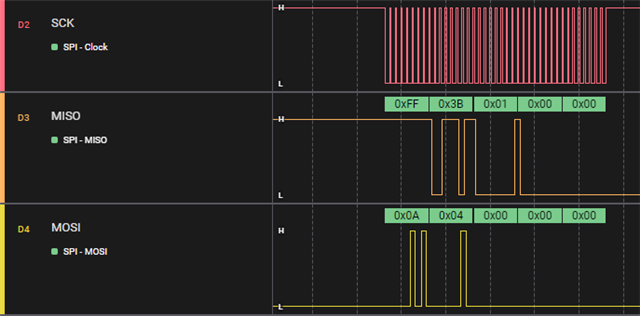
When observing it with the logic analyzer, it looks as though the !CS line never switches low, and nothing else is being transmitted over SPI.

P.S.
The uart version does not seem to work either, is it possible, that for the uart versuion the arduino uart pins in the device tree are incorrect?

  • Hello,

    I don't know this shield specifically, but based on your log, it looks like some of the pins are not responding correctly, or are not set up correctly.

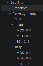
    Perhaps you can show me the device tree pins that you are using? Did you specify them in an overlay file?

    And can you please check nRF Connect for Desktop -> Board Configurator together with the pin description on the back of the DK? Does it look like you are trying to use some of the pins that are also being used for the UART on the DK? Even if you are not using that UART instance specifically, the debugger still may control these pins, so disabling that UART instance in the board configurator in nRF Connect for Desktop may help.

    Best regards,

    Edvin

  • The UART version does start communication over the HCI if I change the UART1 pins from


    RX: P0.28
    TX: P0.29

    to

    RX: P0.00
    TX: P0.01

    But, ultimately, I want to get the SPI version running.
    So that does not help that much.

    You mean overlays other than the one included by using --shield x_nucleo_wba25a1_spi?
    I use the --shield x_nucleo_wba25a1_spi which should include the overlay file for that shield.

    The pins for the SPI seem to be correct.
    If I can trust the silkscreens on the Boards (and the schematics)
    Those should be correct:

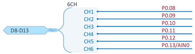
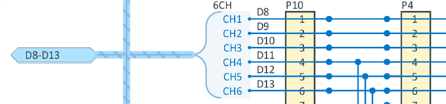
    The Arduino header connects: 
    P0.13 to SCK
    P0.12 to MISO
    P0.11 to MOSI
    P0.10 to NSS

    So this looks correct:


    However, debugging though the code, it looks like the SPI driver tries to do a zero length SPI transfer in order to pull NSS low. This does not seem to have the desired effect, since the transfer including the toggling of the NSS line seems to be completely skipped.

    I tried testing whether this is the root cause by replacing:

    	/* Perform a zero byte SPI transaction to acquire the SPI lock and lower CS
    	 * while waiting for IRQ to be raised
    	 */
    	bt_spi_transceive(header_master, 0, header_slave, 0);

    with

    	#define SPI_NODE DT_NODELABEL(arduino_spi)
    
    	static const struct gpio_dt_spec cs_gpio = GPIO_DT_SPEC_GET(SPI_NODE, cs_gpios);
    	gpio_pin_set_dt(&cs_gpio, 1);
    
    	gpio_pin_interrupt_configure_dt(&irq_gpio, GPIO_INT_DISABLE);
    

    This did cause an SPI transfer which I can not recognize as an HCI command to occur.
    Afterwards the application seems to just hang. There is also no further output.

  • Hello,

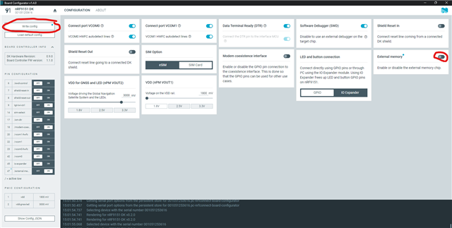
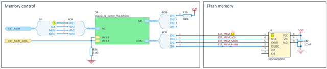
    If you look at the back of the DK, you can see that pins P0.11-13 is connected to the external flash chip on the DK, and not to the pinout. If you want to route these pins out to the pin headers, you need to use the nRF Connect for Desktop -> Board Configurator, and then disable the external flash:

  • I disabled... or... ¿enabled? it.
    No change in behaviour.

    It's a bit confusing, that the entry (47) in the pin configuration table is the inverse of the switch at the right side of the GUI.

    If I send dummy data over the SPI, I can see the data on the MOSI pin on the x_nucleo_wba25a1_spi expansion board, regardless of the external memory interface setting. So the data at least arrives at the arduino expansion header.

    Which if I understand correctly according to you should not actually happen if the memory interface is set "incorrectly"?

    Checking the schematic PCA10171_Schematic_And_PCB.pdf

    Sheet 2, Section 6,7 C


    Sheet 7, Section 1,2,3 C

    Pins P0.08 to P0.13 seems to be directly connected to the arduino expansion header.

    The switch only seems to disconnect the memory itself.


    Sheet 6

    After changing the code to manually set NSS to low I do get a short transmission on MOSI, but nothing further happens.

    So, if you attempt the setup in my OP,
    it works for you after turning of the external memory interface?

    I just ordered some NRF52-DK, since I was told those seem to work out of the box.
    (Which is not really helping with my problem I guess, but now I need to know >_<)

  • YRie said:
    It's a bit confusing, that the entry (47) in the pin configuration table is the inverse of the switch at the right side of the GUI.

    Yes, that is because I didn't write the config yet in that screenshot by clicking the circled "write config" in the upper left corner.

    If it is not properly disconnected, some of the pins may be connected to the external memory, pulling some of them high or low, making them uncontrollable for the nRF91.

    YRie said:
    So, if you attempt the setup in my OP,

    I don't have the shield that you are testing, but it does seem like there is communication on the SPI bus now. Is that the dummy data you are sending, or is that from the shield's drivers? Does the nRF91 behave as it should? Does the BLE shield respond as it should? (I am not familiar with it).

    Best regards,

    Edvin

Related