This post is older than 2 years and might not be relevant anymore
More Info: Consider searching for newer posts

advertising issue with nrf51822 ceaa

image descriptionhello,

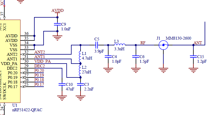
I've encountered a problem with our own nrf51822 circuit not advertising. Our circuit is exactly the same as what is given as the reference circuitry on the datasheet. We tested the exact same code on the nrF51 DK and worked just fine.

Using an enabled debug log support, it says "fast advertising" but nothing appears on our bluetooth list on our phone. We know that the code doesn't hang somewhere because according to the log, the device goes into slow mode exactly after 3 minutes of fast advertising.

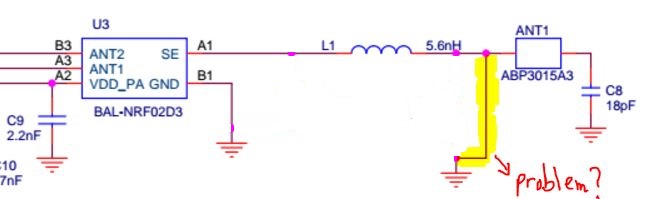
Can you please check my pi-network circuitry? Understanding that it should try to match to 50 Ohms impedance using analyzer and smith chart, would the wire highlighted in yellow on our attached circuit cause our nRF not to advertise at all?

Other significant Information:

  • nRF51822 CEAA package, LDO setup
  • SDK 9.0.0
  • softdevice 110 ver. 8.0.0
  • VDD = 2.5V
  • External 16Mhz works fine (checked it using it as a timer)
  • don't have any button in our circuit
  • want to use both RX and TX (coded in this way)
  • other peripherals such as GPIO and UART work just ok.

I'd appreciate your advice and help.

Thank you in advance!

Parents
  • Hello Alberto, Yes a direct path to GND prior to an Antenna will cause problems. A simple question to ask yourself is what would happen if you shorted your power supply to GND? Bad things... A PI filter should have a cap on each side of the inductor. I am also not understanding the reason for the Balun if you are using the Reference schematic? I might suggest you look at the reference schematic on the DK 51 which is shown below. I can't see what is on the other side of the balun but I have a hunch this is not needed. See the below schematic from the DK 51...

    image description

Reply
  • Hello Alberto, Yes a direct path to GND prior to an Antenna will cause problems. A simple question to ask yourself is what would happen if you shorted your power supply to GND? Bad things... A PI filter should have a cap on each side of the inductor. I am also not understanding the reason for the Balun if you are using the Reference schematic? I might suggest you look at the reference schematic on the DK 51 which is shown below. I can't see what is on the other side of the balun but I have a hunch this is not needed. See the below schematic from the DK 51...

    image description

Children
Related