
Hi
I have a prototype of a board that uses a nNF52832 to communicate over Bluetooth, the board has some buttons intended for user input.
As the board size is little more than the size of the CR2032 powering it the buttons are relatively close to the 32MHz clock crystal, and as a result the users hand will also be in close proximity to the clock and everything else for that matter.
The 2.4GHz part and to some degree the 32MHz clock layout is based of the Nordic reference design and under normal circumstances they work great.
I'm quite impressed / pleased with the Bluetooth range at 0db TX power, the Nordic team has my gratitude for designing the nRF52 and providing the reference design.
However during testing we have found that the Bluetooth link sometimes failed.
It was narrowed down to that the fault occurred while the users was handling cookware on an induction stove while the induction coils was powered and running at a high setting.
The coils operate at roughly 24-48 kHz (can't remember which it is, but its relatively low frequency)
I was able to determine that the most sensitive area seemed to be around the 32MHz crystal oscillator.
At a low but continuous setting on the induction stove I can cause the Bluetooth link to fail by touching and / or being in close proximity to the crystal and the tracks carrying the 32Mhz signal while touching the cookware on a stove.
The issue is easily reproducible while the PCB is located one meter away from the stove. But I can't get it to fail if I don't touch the cookware.
I have therefor concluded that it doesn't seemed to be caused by my hand causing additional capacitive loading on the crystal, thereby causing the Bluetooth link to fail.
It does however seem to be caused by capacitively coupled noise.
Below is a picture of the layout around the 32Mhz clock.
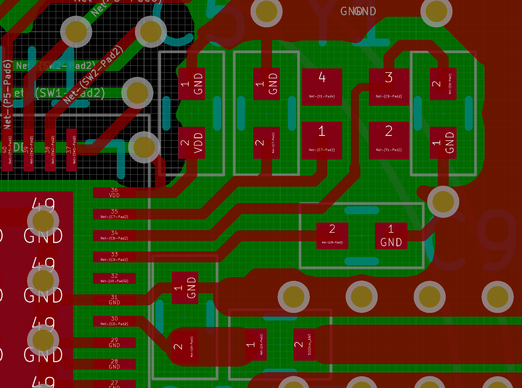
It should be noted that the crystal used is a XRCGB32M000F2P00R0 produced by Murata.
It was chosen for its low price, small size and low CL of 6pF.
It is somewhat odd in that pin 2 and 4 is marked as "No Connect" according to:
www.murata.com/.../productdetail
Also the top metal of the package isn't connected to any pins so it seems.
I have tried to connect the "No Connect" pins to ground but it didn't seem to make the situation better or worse.
It might also be worth noting that I also have made the PCA10036 development kit fail in this way.
But for some reasons an earlier prototype based on an nRF51 module:
www.aliexpress.com/.../32342096215.html
seems to be immune to this problem.
My thoughts:
- Switching to a crystal with a higher CL and resulting bigger capacitors might make it harder to alter the clock signal?
- Switching to a crystal where the case is grounded.
- It should be possible to rearrange the layout to have shorter tracks carrying the 32Mhz clock which is always good.
- Guard ring, the issue doesn't seem to be caused by neighbouring signals, but it might
provide an additional and harmless path for the E-field to follow slightly reducing the impact on the 32MHz signal.
However I'm not too optimistic with regard to this, as the tracks are already relatively close to other "DC" tracks.
Also I won't be able to make a complete ring more like a U shape due to space constraints. - Fitting a metal EMI shield over the PCB.
While this will probably be very efficient and also beneficial for EMC in general, it will incur additional cost so I would rather avoid this if possible.
Anyway I was wondering if anyone on the forums have any suggestions, comments or ideas with regard to that I have missed.
Regards Visti Andresen
