This post is older than 2 years and might not be relevant anymore
More Info: Consider searching for newer posts
This discussion has been locked.
You can no longer post new replies to this discussion. If you have a question you can start a new discussion

problem with ac dimmer circuit with nRF51822

hi,

i tried to make a ac dimmer circuit controlled with dc

i use nrf51822

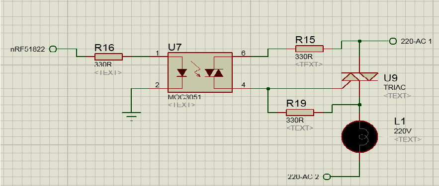
this is my dimmer circuit

image description

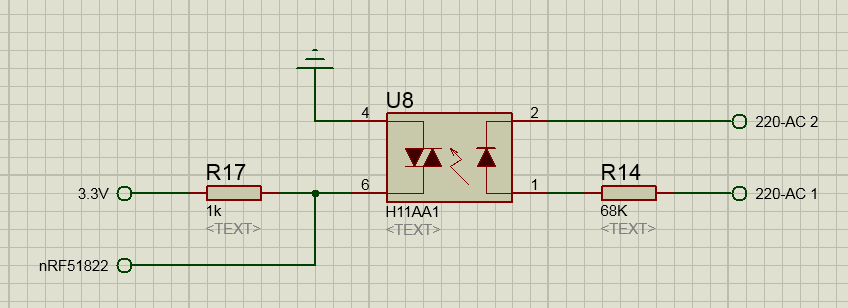
aaand this one is zero crossing detector

image description

finally this is my mbed code;

DigitalOut trigger(p15);

DigitalIn zero(p14);

int main()

{

    while(1)  

    {

        if (zero==1) 

        {

            wait_us (5000);  
                
            trigger = 1;      
             
            wait_us (100);  

            trigger = 0;     

        } 

    }

}

i just want to dim my light %50, but it always blinking.

can anyone help me and tell me what is my mistake?

Parents
  • First of all, the h11aa1 symbol does not seem to be correct. h11aa1 is an AC optocoupler, as can be seen from a quick search on google.

    Second; you have connected the base of the phototransistor, this should in most cases be left open. You should connect the collector (pin 5) to the microcontroller (as can be seen in the google search). With your configuration the zero pin on nRF (p14) is always high, which means that the code will trigger the triac approximately every 5ms.

Reply
  • First of all, the h11aa1 symbol does not seem to be correct. h11aa1 is an AC optocoupler, as can be seen from a quick search on google.

    Second; you have connected the base of the phototransistor, this should in most cases be left open. You should connect the collector (pin 5) to the microcontroller (as can be seen in the google search). With your configuration the zero pin on nRF (p14) is always high, which means that the code will trigger the triac approximately every 5ms.

Children
  • You should also use GPIOTE, TIMER and PPI instead of doing wait_us and polling pin in main. When using code that run asynchronously, like the SoftDevice, this code will not work because interrupts can happen during the wait_us and the timing will be wrong. With GPIOTE, PPI and TIMER the triggering of the triac can happen automatically without using the CPU.

  • ty for reply. actually i made this schematics for question in a rush, and now i see that its pin config wrong, but my circuit desing on board correct, of course i made config by datasheet of h11aa1

    also i detect the zero crossing pulse correctly on a oscilloscope. so my problem on the code part.

  • Do the trigger signal happen 5ms after the zero crossing if you look at the oscilloscope? Are you doing anything else in your code?

  • actually, i look at h11aa1 pulse output at first channel, and AC line second channel, and every 10 ms (zero cross moment) a pulse happend.(in my country freq is 50Hz) but of course trigger pulse isn't happend every 5 ms. code is like i wrote, nothing more or less.

    but after seeing oscilloscope i am sure wrong part is code, right?

  • It looks like that. You have to check the trigger signal on the oscilloscope and check that the trigger signal and the zero crossing signal happens at the correct time.

Related