This post is older than 2 years and might not be relevant anymore
More Info: Consider searching for newer posts

PDM microphone (02730A0019 or AKU242) electrical connection to nRF52832

Hi,

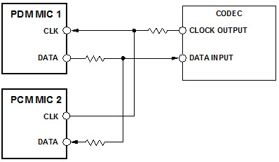
I am connecting the AKU242 straight to our microprocessor. It is a PDM interface so it has a SELECT, DATA, CLOCK, VDD and 5 GND signals. On the datasheet, there are two identical PDM microphones with one SELECT connected to GND and another SELECT connected to VDD.

  1. However, we have only ONE PDM microphone on our system. Any recommendation on how to connect the SELECT of the microphone?

Also:

  1. Do we need any resistors (~50 Ohms) on the DATA/CLK lines on microphone to PDM-DATA/PDM-CLK on nordic?

Thanks!

Parents
  • Hi,

    1. If you take a look at the datasheet it actually says L/R SELECT. So this line determines if the microphone is left or right. See here for hardware examples using PDM.

    2. Resistors should not be necessary in theory, but if the lines are long or there is much noise you may want to have resistors on the lines. Because of this I would recommend to start with 0 ohm resistors and if you have problems try to change them out with for example 50 ohm resistors (20 – 100 ohm should be good). The resistor on the CLOCK line should be close to the nRF and the resistors on the DATA line should be close to the PDM chip, like this.

Reply
  • Hi,

    1. If you take a look at the datasheet it actually says L/R SELECT. So this line determines if the microphone is left or right. See here for hardware examples using PDM.

    2. Resistors should not be necessary in theory, but if the lines are long or there is much noise you may want to have resistors on the lines. Because of this I would recommend to start with 0 ohm resistors and if you have problems try to change them out with for example 50 ohm resistors (20 – 100 ohm should be good). The resistor on the CLOCK line should be close to the nRF and the resistors on the DATA line should be close to the PDM chip, like this.

Children
Related