This post is older than 2 years and might not be relevant anymore
More Info: Consider searching for newer posts

QFAC QFN48 schematic with DC/DC converter setup

Hi,

I want to implement a DC/DC converter setup schematic for my projet and I don't know how to make the difference between the AVDD and VCC_nRF supply tags given in the datasheet "nRF51822_PS_v3.1" page 95.

image description

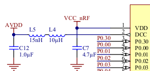
I intend to use a 3.3V voltage supply given by a buckboost converter.

What kind of electrical circuit should I use for the VCC_nRF and VDD in order to power the nRF51822 with the DC/DC converter setup correctly?

Parents
  • So you are using an external DC/DC converter? AVDD is as the datasheet says “Analog power supply (radio)”. The internal DC/DC converter on nRF51 can be used to power the radio. See the Reference Manual chapter 12.1.3. To reduce current consumption and the BOM, you may want to consider to have supply voltage down to 1.8V instead, which is the lowest voltage the nRF51 can operate. The gpio voltage will be the same as the supply voltage so you will have to check that other chips in the system will still work at 1.8V. The internal DC/DC regulator is efficient down to about 2.1V.

Reply
  • So you are using an external DC/DC converter? AVDD is as the datasheet says “Analog power supply (radio)”. The internal DC/DC converter on nRF51 can be used to power the radio. See the Reference Manual chapter 12.1.3. To reduce current consumption and the BOM, you may want to consider to have supply voltage down to 1.8V instead, which is the lowest voltage the nRF51 can operate. The gpio voltage will be the same as the supply voltage so you will have to check that other chips in the system will still work at 1.8V. The internal DC/DC regulator is efficient down to about 2.1V.

Children
No Data
Related