I have an implementation that is using a PWM output to drive a LED. It has been observed that when the LED is on in a constant drive state, fixed PWM output train, the LED will "flash". i.e. change intensity for a short period, and then return to the correct output level. This happens at a very sporadic and infrequent rate. I had a capture of the PWM output on scope, and did not properly save it, so I am working on getting one to post with this question.
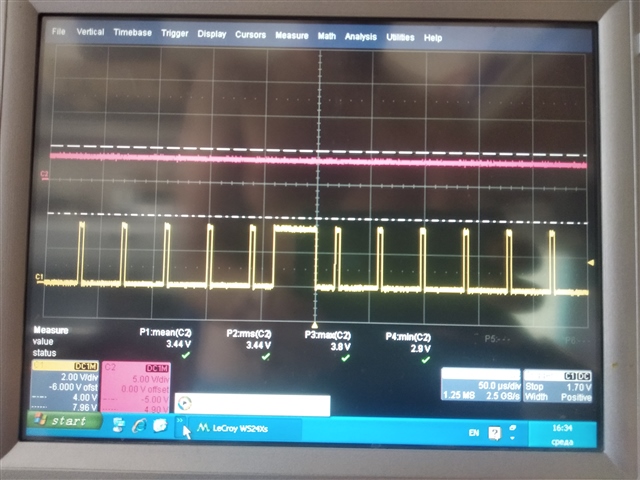
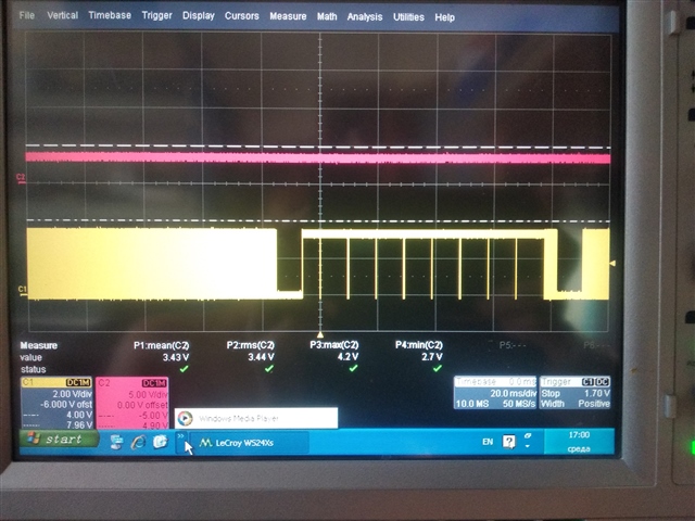
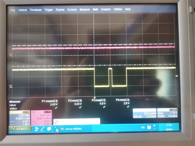
What is observed in the trace that I did have, is a singular event in the pulse train, which looks like the PWM module misses the "off" trigger, and carries the output in the "on" state until the point in time that the next "off" trigger would occur. The PWM module then shuts off the output and continues operating correctly from that point, until some random point in the future. The output is running a fairly show 150 Hz PWM period, which we have cut into 255 DC elements. There is not change in the observed period frequency during this event. The PWM is running a simple playback, single PWM value task. I have instrumented all of the change vectors, and nothing from the software side is directing a change during this operation.
The system is running SD132 and using SDK 11 release. We are running the radio in advertising and also connected modes. It is not clear yet if this has any effect on the problem.
The question in this would be, is there some hardware path that could allow the system to miss a counter crossing event? It seems that the PPI and task system should handle this without interference from other hardware elements, but maybe there is something not apparent.
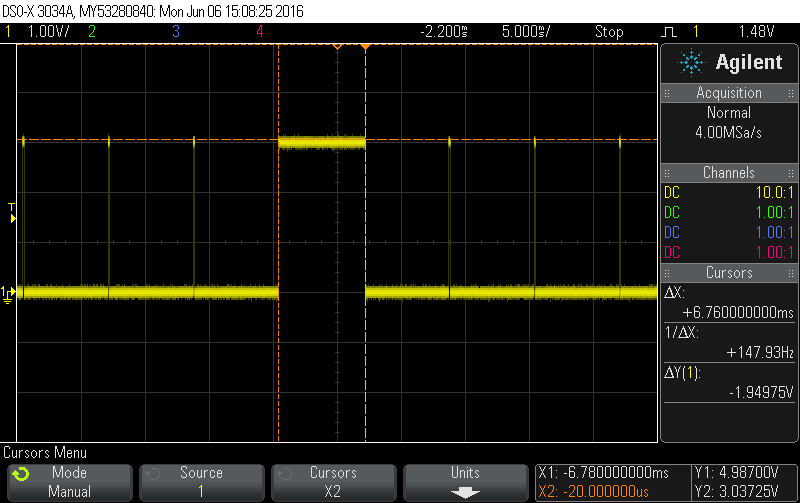
Update: Ok, I got my scope image. Took awhile. The trace shows the 100us pulses running at 6.660ms period. The single outlier is 6.76ms in width, or as described above, it looks like the hardware missed the shutoff for a single period, then picked back up running.

Update for Code: Adding a snippet of code for Ole. Configuration of the SD Clock and then the setup for the PWM control.
#define NRF_CLOCK_LFCLKSRC      {.source        = NRF_CLOCK_LF_SRC_XTAL,            \
                             .rc_ctiv       = 0,                                \
                             .rc_temp_ctiv  = 0,                                \
                             .xtal_accuracy = NRF_CLOCK_LF_XTAL_ACCURACY_20_PPM}
Setup for PWM
#define HL_NUM_LED_PWM_STEPS (255)

        static nrf_drv_pwm_t m_LED_pwm     = NRF_DRV_PWM_INSTANCE(0);
        static nrf_drv_pwm_config_t const m_LED_config =
        {
            .output_pins =
            {
                OUTPUT_LED_ENABLE_PWM_PIN, // channel 0
                NRF_DRV_PWM_PIN_NOT_USED, // channel 1
                NRF_DRV_PWM_PIN_NOT_USED, // channel 2
                NRF_DRV_PWM_PIN_NOT_USED  // channel 3
            },
            .base_clock = NRF_PWM_CLK_250kHz,
            .count_mode = NRF_PWM_MODE_UP,
            .top_value  = 1667,
            .load_mode  = NRF_PWM_LOAD_INDIVIDUAL,
            .step_mode  = NRF_PWM_STEP_AUTO
        };
        static nrf_pwm_values_individual_t m_LED_seq_values =
        {
            .channel_0 = 0,
            .channel_1 = 0,
            .channel_2 = 0,
            .channel_3 = 0
        };
        static nrf_pwm_sequence_t const m_LED_channel_seq =
        {
            .values.p_individual = &m_LED_seq_values,
            .length              = NRF_PWM_VALUES_LENGTH(m_LED_seq_values),
            .repeats             = 0,
            .end_delay           = 0
        };
    static nrf_pwm_edge_t m_LED_polarity = NRF_PWM_EDGE_FALL;
Init and call to start the action
err_code = nrf_drv_pwm_init(&m_LED_pwm, &m_LED_config, NULL);
APP_ERROR_CHECK(err_code);

ledDriverSequenceCounts = (uint16_t)((uint32_t)ledDriverPwmCounts * m_LED_config.top_value / (uint32_t)HL_NUM_LED_PWM_STEPS);
ledDriverSequenceCounts |= m_LED_polarity;
m_LED_seq_values.channel_0 = ledDriverSequenceCounts;
nrf_drv_pwm_simple_playback(&m_LED_pwm, &m_LED_channel_seq, 1, NRF_DRV_PWM_FLAG_LOOP);
For the testing, I am just manually setting the PWM input to a value that make the glitch artifact visible, and then it is never changed again. I also tried longer PWM DC settings, thinking there might be something in the short 140us duration, but I also see it glitch out to over a 1ms DC within the 6.66ms period. As you said, mostly very infrequently, but sometimes "quickly" in succession.
Regards, Michael


