Hi,
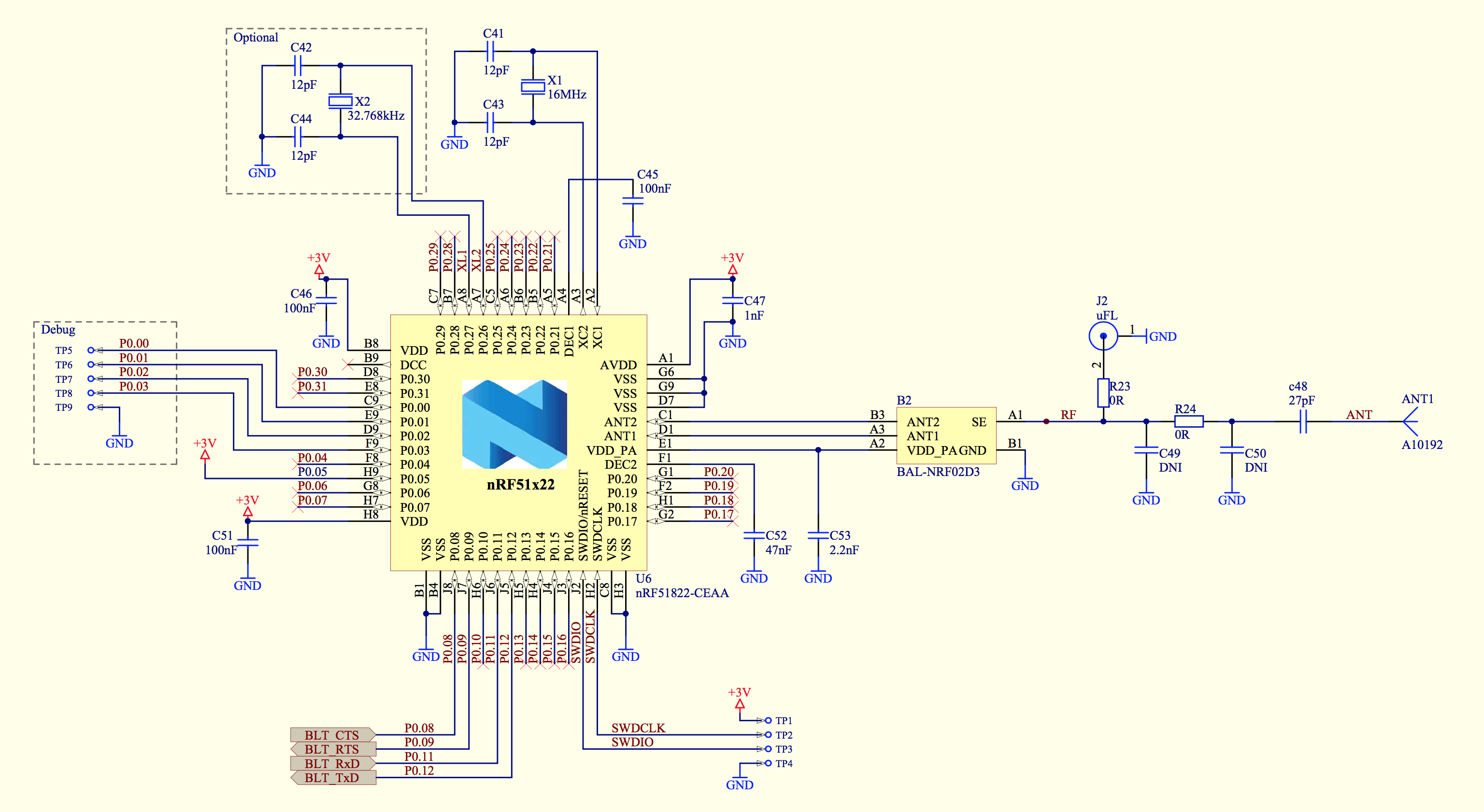
we integrated in a board design the one of the nRF51822 proposed by Nordic. It is written on the chip:
- N51822
- CEAAO1
- 1401AA
I can flash my board using the nRF51 DK without problem. It detects that an external board is plugged and I can flash my board via the DK.
However, the SW doesn't seems to run. I tried the debugger (Eclipse/OS X): flashing works fine but debugging doesn't work. I get: Unable to retrieve disassembly data from backend.
So I have the following questions:
- Can the same SW be flashed for DK & my board?
- Can the same soft device be used? (components/softdevice/s130/hex/s130_nrf51_2.0.0_softdevice.hex)
- I suspect the 16MHz to do not oscillate. It is used during flashing?
I have annexed the flashing traces.
Thanks in advance for your help.
Bernard
% make flash_softdevice
Flashing: s130_nrf51_2.0.0_softdevice.hex
/usr/local/bin/nrfjprog --program ../../../components/softdevice/s130/hex/s130_nrf51_2.0.0_softdevice.hex -f nrf51 --chiperase
Parsing hex file.
Erasing code and UICR flash areas.
Applying system reset.
Checking that the area to write is not protected.
Programing device.
/usr/local/bin/nrfjprog --reset -f nrf51
Applying system reset.
Run.
% make flash
Linking target: nrf51422_xxac_s130.out
Preparing: nrf51422_xxac_s130.bin
Preparing: nrf51422_xxac_s130.hex

   text	   data	    bss	    dec	    hex	filename
  43472	    128	   3436	  47036	   b7bc	_build/nrf51422_xxac_s130.out

Flashing: _build/nrf51422_xxac_s130.hex
/usr/local/bin/nrfjprog --program _build/nrf51422_xxac_s130.hex -f nrf51  --sectorerase
Parsing hex file.
Erasing page at address 0x1B000.
Erasing page at address 0x1B400.
Erasing page at address 0x1B800.
Erasing page at address 0x1BC00.
Erasing page at address 0x1C000.
Erasing page at address 0x1C400.
Erasing page at address 0x1C800.
Erasing page at address 0x1CC00.
Erasing page at address 0x1D000.
Erasing page at address 0x1D400.
Erasing page at address 0x1D800.
Erasing page at address 0x1DC00.
Erasing page at address 0x1E000.
Erasing page at address 0x1E400.
Erasing page at address 0x1E800.
Erasing page at address 0x1EC00.
Erasing page at address 0x1F000.
Erasing page at address 0x1F400.
Erasing page at address 0x1F800.
Erasing page at address 0x1FC00.
Erasing page at address 0x20000.
Erasing page at address 0x20400.
Erasing page at address 0x20800.
Erasing page at address 0x20C00.
Erasing page at address 0x21000.
Erasing page at address 0x21400.
Erasing page at address 0x21800.
Erasing page at address 0x21C00.
Erasing page at address 0x22000.
Erasing page at address 0x22400.
Erasing page at address 0x22800.
Erasing page at address 0x22C00.
Erasing page at address 0x23000.
Erasing page at address 0x23400.
Erasing page at address 0x23800.
Erasing page at address 0x23C00.
Erasing page at address 0x24000.
Erasing page at address 0x24400.
Erasing page at address 0x24800.
Erasing page at address 0x24C00.
Erasing page at address 0x25000.
Erasing page at address 0x25400.
Erasing page at address 0x25800.
Applying system reset.
Checking that the area to write is not protected.
Programing device.
/usr/local/bin/nrfjprog --reset -f nrf51
Applying system reset.
Run.
%"


