
Hello,
I want to use SPI between one nRF51-DK (using SD130 v 2 and SDK11) and another board. I am supplying the nRF with 2.3 V and initializing the BLE and the SPI. I can connect via BLE to other nRF but I can't send or receive data from the other board through SPI. From what I discovered, the problem is on the SPI clock which is not starting at all. It is giving me 0 V.
I'll attach my code for the SPI initialization, and for the pins configuration.
	//SPI
#define SPI_MASTER_SCK_PIN					(8U)//(2U)
#define SPI_MASTER_CS_PIN					(9U)//(3U)
#define SPI_MASTER_MISO_PIN					(10U)//(4U)
#define SPI_MASTER_MOSI_PIN					(11U)//(5U)

 static void spi_init(void)
 {
 /* 		**SPI inits**				*/
	nrf_drv_spi_config_t spi_config = NRF_DRV_SPI_DEFAULT_CONFIG(SPI_INSTANCE);	//setting default values

  /*				nrf_gpio_cfg_output(SPI_MASTER_SCK_PIN);
    nrf_gpio_cfg_output(SPI_MASTER_MOSI_PIN);
    nrf_gpio_cfg_input(SPI_MASTER_MISO_PIN, NRF_GPIO_PIN_NOPULL);
    nrf_gpio_cfg_output(SPI_MASTER_CS_PIN);*/
	//setting the values that we want for the pins
	spi_config.sck_pin 	= SPI_MASTER_SCK_PIN;
	spi_config.miso_pin = SPI_MASTER_MISO_PIN;
	spi_config.mosi_pin = SPI_MASTER_MOSI_PIN;
	spi_config.ss_pin 	= SPI_MASTER_CS_PIN;

	spi_config.frequency = NRF_DRV_SPI_FREQ_2M;
	spi_config.mode = NRF_DRV_SPI_MODE_1;
	//initializing the spi communication bus
	APP_ERROR_CHECK(nrf_drv_spi_init(&spi, &spi_config, spi_event_handler));
 }
I already tried to change the pins to several others, and i can see that the MOSI and CS Pin work (Miso I can't see it work because I'm not connecting to anything when trying to debug), but the clock stays the same, always as 0V. Am I configuring wrongly the pins, or the SPI initiaization? Do I need to add something so the clock starts?
I searched for some questions about this, but couldn't find any information. Thanks for the help
EDIT1: I changed my program to set the CS pin to low when I want to transfer and back to high when I want him to stop. There is now a clock signal but is a strange signal, the maximum it gets is 700 mV and the low part is on 300 mV. I'll try to print the images I get on the oscilloscope to put here.
Images:
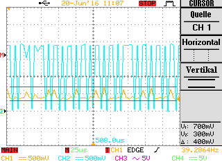
CH1 = SPI_CLK CH2 = SPI_MOSI
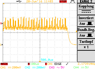
CH1 = SPI_CLK
From what I can understand, the shape of the SPI_CLK is very strange.
