This post is older than 2 years and might not be relevant anymore
More Info: Consider searching for newer posts

Pixel display on Sharp Memory LCD with nRF51

Hi,

I am coding a Sharp memory LCD display using SPI and the nRF51422 development board.

I have tested the SPI connection using a logic analyzer and signals are being sent to clk, chip select and MOSI pins.

However, I cannot get meaningful images to appear on the screen. Only random dots appear on the screen after programming the nRF51 and turning it on and off.

In the attached IAR code, I am trying to write a line of 0's and 1's to line 1 of the 96x96 screen.

The SPI CLK has been tested at 8MHz, 1MHz and 125kHz, but the screen does not function in any of these cases.

IAR full workspace: spi_master.eww

main.c: main.c

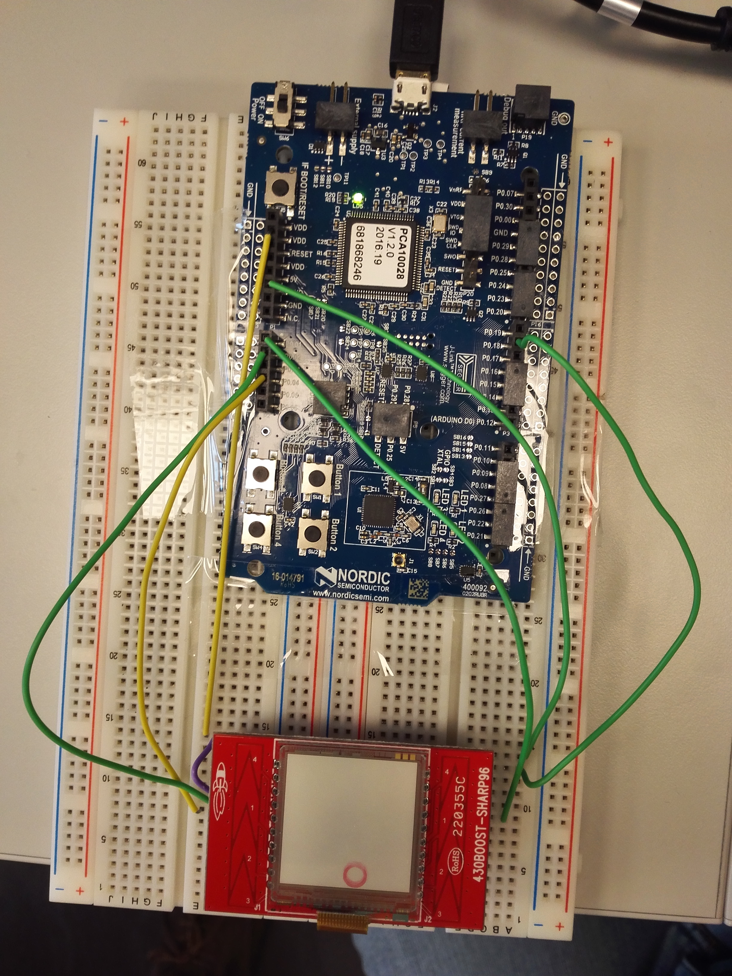
Picture of connections between LCD and nRF51422: LCD.jpg

Datasheet for Sharp Memory LCD boosterpack: TI booster pack slau553.pdf

Document for protocols in writing data to LCD: programming_memory_lcd_app_note.pdf

Parents
  • Hi,

    I've used a similar display in the past, but unfortunately can't provide the full source code.

    From your init_buf() routine, it looks like you're trying to write alternating 1's and 0's to line 1 correct? From page 4 of the "programming memory lcd app note" pdf, it states that the write line "payload" consists of 4 distinct parts - The command, the line number, the data and the trailer.

    So the write line command starts with 0x80 or'd with the current status of the vcom bit. So in your init_buf() routine, I think you need

    p_tx_buf[0] = 0x80 | (v_bit << 6)
    

    instead of what you have

    p_tx_buf[0] = 0xa0 | (v_bit << 6)
    

    Also, the 2nd byte you're sending (the line address byte) needs to be swapped (so MSB goes to LSB, et cetera). This is seen in page 7 of the app note and n your case I think you'd want...

    p_tx_buf[1] = (0x80);
    

    Then you should be able to transfer the rest of your data buffer and trailer bytes.

    If all of that fails, see if you can get the clear screen command to work then build up from there. Your spi tx buffer should only consist of the clear command and one trailer byte

    p_tx_buf[0] = (v_bit << 6) | 0x20;  // 0x20 is clear memory command
    p_tx_buf[1] = 0x00;
    

    and change the appropriate 'len' variables

    **Edit: ** Changed from (1<<7) to (1<<6) for the vcom bit

Reply
  • Hi,

    I've used a similar display in the past, but unfortunately can't provide the full source code.

    From your init_buf() routine, it looks like you're trying to write alternating 1's and 0's to line 1 correct? From page 4 of the "programming memory lcd app note" pdf, it states that the write line "payload" consists of 4 distinct parts - The command, the line number, the data and the trailer.

    So the write line command starts with 0x80 or'd with the current status of the vcom bit. So in your init_buf() routine, I think you need

    p_tx_buf[0] = 0x80 | (v_bit << 6)
    

    instead of what you have

    p_tx_buf[0] = 0xa0 | (v_bit << 6)
    

    Also, the 2nd byte you're sending (the line address byte) needs to be swapped (so MSB goes to LSB, et cetera). This is seen in page 7 of the app note and n your case I think you'd want...

    p_tx_buf[1] = (0x80);
    

    Then you should be able to transfer the rest of your data buffer and trailer bytes.

    If all of that fails, see if you can get the clear screen command to work then build up from there. Your spi tx buffer should only consist of the clear command and one trailer byte

    p_tx_buf[0] = (v_bit << 6) | 0x20;  // 0x20 is clear memory command
    p_tx_buf[1] = 0x00;
    

    and change the appropriate 'len' variables

    **Edit: ** Changed from (1<<7) to (1<<6) for the vcom bit

Children
No Data
Related