
I'll try to simplify my project as much as possible to make this understandable. I'm wiring an nRF52 PCA10040 board to an iCE5LP (Lattice) FPGA.
I'm having an issue with the bytes coming in to the MCU (MISO line), here's the course of action:
- Master sends command through SPI
- Slave executes the command, and prepare data for transfer
- After waiting long enough for the command to be processed and the data to be prepared, the Master sends dummy bytes to receive the tx register from the FPGA.
- Data looks shifted, and is inconsistent.
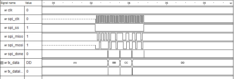
The data is properly loaded, according to the simulation. What I receive every other transfer is the byte I'm expecting but shifted by one bit. See the following screenshots;
This is the simulation:
This is the output from the logic analyzer:
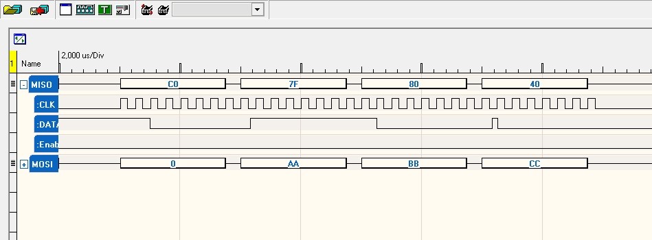
What I expect: (it's an eMMC initialization procedure)
- 0xC0FF8080 or 0x40FF8080 depending on the init result
What I get randomly:
- 0xE07FC040 which is 0xC0FF8080 >> 1
- 0x007F8040 which is 0x00FF0080 >> 1
    static uint8_t       m_rx_buf[4];        /** 31 || module > 7) {
    		return APP_ERROR_INVALID_CMD;
    	}

    	uint8_t msg_a[] = {firstByte, mmc_command, mmc_arg >> 24, mmc_arg >> 16,  mmc_arg >> 8, mmc_arg & 0xFF};
    	uint8_t msg_length = sizeof(msg_a);

    	memset(m_rx_buf_ext, 0, msg_length);

    	spi_xfer_done = false;

    	err_code = nrf_drv_spi_transfer(&spi, msg_a, msg_length, m_rx_buf_ext, msg_length);
    	while (!spi_xfer_done) {
    		__WFE();
    	}
    	if (err_code != NRF_SUCCESS) {
    		NRF_LOG_PRINTF("Error during transfer : %d\n", err_code);
    	}
    	return err_code;
    }


    ret_code_t initMMC() {
    	ret_code_t err_code;
    	bool mmc_initialized = false;

    	nrf_delay_us(200);	/**LFCLKSRC            = (CLOCK_LFCLKSRC_SRC_Xtal <EVENTS_LFCLKSTARTED = 0;
    	NRF_CLOCK->TASKS_LFCLKSTART    = 1;
    	while (NRF_CLOCK->EVENTS_LFCLKSTARTED == 0); // Wait for clock to start
    }


    int main(void) {
    	APP_ERROR_CHECK(NRF_LOG_INIT());
    	init_clock();
    	LEDS_CONFIGURE(LEDS_MASK);
    	LEDS_OFF(LEDS_MASK);
    	APP_TIMER_INIT(APP_TIMER_PRESCALER,APP_TIMER_OP_QUEUE_SIZE,NULL);
    	APP_ERROR_CHECK(nrf_drv_gpiote_init());
    	buttons_init();
    	NRF_LOG_PRINTF(NRF_LOG_COLOR_RED"\nSTARTING.\r\n"NRF_LOG_COLOR_DEFAULT);

    	nrf_drv_spi_config_t spi_config = NRF_DRV_SPI_DEFAULT_CONFIG(SPI_INSTANCE);
    	spi_config.ss_pin = SPI_CS_PIN;
    	spi_config.frequency = NRF_SPI_FREQ_4M;
    	spi_config.mode = NRF_DRV_SPI_MODE_0;
    	APP_ERROR_CHECK(nrf_drv_spi_init(&spi, &spi_config, spi_event_handler));

    	resetFPGA(RST_PIN); 		//Pulls up fpga's reset pin for 5ms then down
    	nrf_delay_ms(1000);

    	APP_ERROR_CHECK(initMMC());
    	while(1) {
    		__WFE();
    	}
    }
Do you have an idea on what I'm doing wrong?
EDIT: About the clocks: The FPGA's clock is 12MHz, SPI is 4MHz.
