This post is older than 2 years and might not be relevant anymore
More Info: Consider searching for newer posts

I2S 32-bit word size

Hello,

I am struggling with interfacing an I2S digital microphone to the nRF52. To be more concrete, it is the Knowles SPH0645LM4H-B. I connected it as suggested in this thread. In the data sheet of the microphone it says:

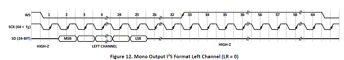
The SPH0645LM4H microphone operates as an I2S slave. The master must provide the BCLK and WS signals. The Over Sampling Rate is fixed at 64 therefore the WS signal must be BCLK/64 and synchronized to the BCLK. Clock frequencies from 2.048Mhz to 4.096MHz are supported so sampling rates from 32KHz to 64KHz can be had by changing the clock frequency. The Data Format is I2S, 24 bit, 2’s compliment, MSB first. The Data Precision is 18 bits, unused bits are zeros.

I find this contradictory with the figure also provided in the data sheet of the microphone:

image description

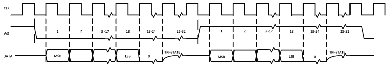
In the image it is clear to see that WS toggles first after 32 clocks, which -for me- means, the word size is 32 bits (18 bits data, 6 bits set to 0, and 8 further bits floating).

The problem is that the nRF52's I2S interface does not support 32-bit word size.

/**
 * @brief I2S sample widths.
 */
typedef enum
{
    NRF_I2S_SWIDTH_8BIT  = I2S_CONFIG_SWIDTH_SWIDTH_8Bit,  ///< 8 bit.
    NRF_I2S_SWIDTH_16BIT = I2S_CONFIG_SWIDTH_SWIDTH_16Bit, ///< 16 bit.
    NRF_I2S_SWIDTH_24BIT = I2S_CONFIG_SWIDTH_SWIDTH_24Bit,  ///< 24 bit.
} nrf_i2s_swidth_t;

No matter what settings I try with the available 8, 16, or 24 bit word-size, I can't get all the relevant data bits from the microphone's data stream.

Any ideas how to solve this problem? Or are these two components (nRF52 and Knowles mic) simply incompatible?

Thank you in advance! NewtoM

  • Hello, This seems to be a major issue with the nRF52 I2S not supporting a 32bit Data length. Every I2S Digital Microphone that is referenced in these forum posts(ICS-43432 & SPH0645LM4H-B) require 32 clocks for both the left and right signals regardless if the Data itself is only 24bits. The 32 clocks is what is expected to alternate the WS/LRCLK signal between the Left and Right channels. Without being able to define the sample width to be 32bits it does not seem to be possible to ever get the I2S module to work with any of these I2S output Microphones as the Data Width definition is directly related to how many clocks are presented for each channel. image description

    So my question is whether or not this is a matter that can be resolved by a SDK update or if the 24bit DataWidth is hard fixed in the I2S silicon on the nRF52. If it is hard-fixed there does not appear to be hope to be able to use any of these I2S Digital output microphones with the nRF52...and off to using the less than preferred PDM method.

    Regards, Frank

  • Hi Frank,

    The nRF52832 only supports 32 bit width in I2S-slave mode. I will report this back to our product management, so that they can take this into consideration in the future.

    Best regards, Håkon

  • Hi Hakon,

    I am trying to use the I2S with DA7210. With my previous MCU I used the configuration:

    • MCU I2S master; CODEC I2S slave
    • sample rate: 32kpbs
    • 24 bit (in 32 bit two's complement with sigh extension)
    • MSB align
    • Stereo
    • Master CLK provided by MCU with ratio 256x (32kpbs x 256 = 8.192MHz)

    For that I tried to modify the example for pca10040 (I have a board with nRF52832) with nRF5x MDK 8.11.1 IAR + IAR 7.5

    When I tried to use this configuration I was unable to set the I2S.

    Questions:

    1. Can I use this configuration? The MCLK max speed (according to nRF52832_OPS_v0.6.2.pdf) is max 4Mhz (I need 8Mhz) - but according to nRF52832_PS_v1.0.pdf is a valid example (shown in table 101).

    2. Apparently the 24 bit limitation comes from driver: In library is hard coded to reject the configuration 24 bit with RATIO_256X. ((sample_width == NRF_I2S_SWIDTH_24BIT) && ((ratio == NRF_I2S_RATIO_32X) || (ratio == NRF_I2S_RATIO_64X) || (ratio == NRF_I2S_RATIO_128X) || (ratio == NRF_I2S_RATIO_256X) || (ratio == NRF_I2S_RATIO_512X)))) Also 16 bits has some limitations: ((sample_width == NRF_I2S_SWIDTH_16BIT) && (ratio == NRF_I2S_RATIO_48X))

    3. Another problem I have is that even with 16 bits is not reading the data back correctly if I connect the scope (10pF , 1Mohm) to I2C_SCK. Below you have the log. I don't understand why behaves like that ... is like the bytes are delayed. In the end we have overflow.

      APP:INFO: 1: 0000/cafd, expected: cafd/caff APP:INFO: 1: caff/cafe, expected: cafe/cb00 APP:INFO: 1: cb00/caff, expected: caff/cb01 APP:INFO: 1: cb01/cb00, expected: cb00/cb02 APP:INFO: 1: cb02/cb01, expected: cb01/cb03 APP:INFO: 1: cb03/cb02, expected: cb02/cb04 APP:INFO: 1: cb04/cb03, expected: cb03/cb05 APP:INFO: 1: cb05/cb04, expected: cb04/cb06 APP:INFO: 1: cb06/cb05, expected: cb05/cb07 APP:INFO: 1: cb07/cb06, expected: cb06/cb08 APP:INFO: 1: cb08/cb07, expected: cb07/cb09 APP:INFO: 1: cb09/cb08, expected: cb08/cb0a APP:INFO: 1: cb0a/cb09, expected: cb09/cb0b APP:INFO: 1: cb0b/cb0a, expected: cb0a/cb0c APP:INFO: 1: cb0c/cb0b, expected: cb0b/cb0d APP:INFO: 1: cb0d/cb0c, expected: cb0c/cb0e APP:INFO: 1: cb0e/cb0d, expected: cb0d/cb0f APP:INFO: 1: cb0f/cb0e, expected: cb0e/cb10 APP:INFO: 1: cb10/cb0f, expected: cb0f/cb11 APP:INFO: 1: cb11/cb10, expected: cb10/cb12 APP:INFO: 1: cb12/cb11, expected: cb11/cb13 APP:INFO: 1: cb13/cb12, expected: cb12/cb14 APP:INFO: 1: cb14/cb13, expected: cb13/cb15 APP:INFO: 1: cb15/cb14, expected: cb14/cb16 APP:INFO: 1: cb16/cb15, expected: cb15/cb17 APP:INFO: 1: cb17/cb16, expected: cb16/cb18 APP:INFO: 1: cb18/cb17, expected: cb17/cb19 APP:INFO: 1: cb19/cb18, expected: cb18/cb1a APP:INFO: 1: cb1a/cb19, expected: cb19/cb1b APP:INFO: 1: cb1b/cb1a, expected: cb1a/cb1c APP:INFO: 1: cb1c/cb1b, expected: cb1b/cb1d APP:INFO: 1: cb1d/cb1c, expected: cb1c/cb1e APP:INFO: 1: cb1e/cb1d, expected: cb1d/cb1f APP:INFO: 1: cb1f/cb1e, expected: cb1e/cb20 APP:INFO: 1: cb20/cb1f, expected: cb1f/cb21 APP:INFO: 1: cb21/cb20, expected: cb20/cb22 APP:INFO: 1: cb22/cb21, expected: cb21/cb23 APP:INFO: 1: cb23/cb22, expected: cb22/cb24 APP:INFO: 1: cb24/cb23, expected: cb23/cb25 APP:INFO: 1: cb25/cb24, expected: cb24/cb26 APP:INFO: 1: cb26/cb25, expected: cb25/cb27 APP:INFO: 1: cb27/cb26, expected: cb26/cb28 Overflow Overflow Overflow Overflow

    This is the way I configured the I2S:

    config.sck_pin   = 31; //I2S_CONFIG_SCK_PIN;
    config.lrck_pin  = 30; //I2S_CONFIG_LRCK_PIN;
    config.mck_pin   = 27; //I2S_CONFIG_MCK_PIN;
    config.sdout_pin = 29; //I2S_SDOUT_PIN;
    config.sdin_pin  = 28; //I2S_SDIN_PIN;
    config.irq_priority = 0;
    config.mode      = NRF_I2S_MODE_MASTER;
    config.format    = NRF_I2S_FORMAT_ALIGNED;
    config.alignment = NRF_I2S_ALIGN_LEFT;
    config.sample_width = NRF_I2S_SWIDTH_16BIT;
    config.channels  = NRF_I2S_CHANNELS_STEREO;
    config.mck_setup = NRF_I2S_MCK_32MDIV4;
    config.ratio     = NRF_I2S_RATIO_256X;
    

    This configuration is OK?

    Thank you,

    Alin

  • Hello All,

    I think there is a work-around of sorts now that addresses the issues experienced here... Specifically, the term "24-bit" is misleading. 24-bit I2S microphones output 24 data bits per stereo channel but require 32 SCK pulses per channel to function properly. So, the stereo I2S frame needs to be 64 SCK pulses wide. Like everyone else, I was attempting to collect audio data from a modern 24-bit I2S MEMS microphone and ran into the hard-coded limitation of 48 SCK pulses per stereo I2S frame in I2S master mode. The I2S frame will never be 64 SCK pulses wide In master mode but in I2S slave mode the nRF52 will properly decode the 24 data bits per channel even if the the frame is 64 SCK pulses wide. After reading the I2S protocol spec, It dawned on me that there really is precious little difference between I2S master and slave modes... Just where the LRCK and SCK pulses come from.

    My solution was to augment the PWM library to set the PWM carrier period directly in 16MHz ticks, not milliseconds. So I use two PWM channels; one to generate SCK and the other to generate LRCK and connect the PWM outputs to the I2S SCK and LRCK pins. I set the LRCK PWM channel period to be 64X that of the SCK PWM chanel period. I have a functioning peripheral application for SDK 13.0.0 and the pca10040 DK board located here:

    github.com/.../nRF52_24-bit-_I2S_Microphone_Audio_Recording_Utility

    I was using the Invensense ICS43432 microphone. There is a sample ".wav" audio file that demonstrates typical audio quality....

    This may be considered as an ugly work-around but it does work and doesn't require any other external devices to generate the clock signals...

    Best Regards, Greg Tomasch

  • Does anyone know if this I2S Master clock issue has been addressed (fixed) in the nRF-52840 device?

Related