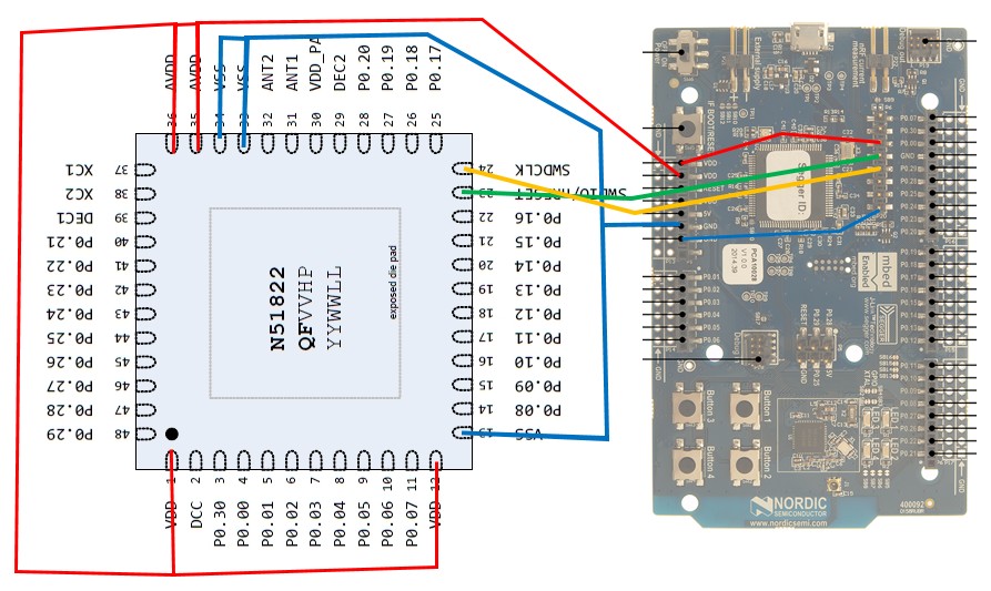
Hi!
I have trouble in flashing a simple nrf51822 via the nrf51-dk.
Can anyone ensure me that this simple wiring should be able to upload an hex file onto the nrf51822 ship?

Thanks in advance for you response! Fred
Hi!
I have trouble in flashing a simple nrf51822 via the nrf51-dk.
Can anyone ensure me that this simple wiring should be able to upload an hex file onto the nrf51822 ship?

Thanks in advance for you response! Fred
That looks correct to me. I assume that the chip has decoupling capacitors connected on the DEC pins according to the reference design.
Do you see the chip in for example nrfGo studio, or can you do simple commands like reset with nrfjprog: nrfjprog -r?
Hi and thank you for your answer! I am still not able to flash one of my external ship... Do you mean that the two capacitors on DEC1 and DEC2 are mandatory in order to get the external ship working? Do you know if there are other things missing on my schematic? thanks
Decoupling capacitors is always important in embedded designs and not including them may lead to the chip not working at all. The capacitors should be placed as close to the DEC pins as possible. You should also have decoupling capacitors on VDD pins, see the reference design (the reference desing should be copied in most cases to get the optimal performance).
DEC1 and DEC2 are for the system and peripheral power and flash power respectively, see the Reference Manual chapter 12 Power management (POWER).
I based my design on the reference one this should be ok, my objective is to test the ship soldering before to sold all the others capacitor, oscillator, etc... that's why I wanted to know what are the minimum additional components required in order just to flash the ship. I already test with the capacitor C8 and C10 on the DEC1 and DEC2 but it doesn't work... I will test asap by adding also the C7, C11 and C9 but I tough they are not fully mandatory as I though they are here just to stabilise the power. Thanks!
hi Flagada15 how did it go? did you find your problem?