This post is older than 2 years and might not be relevant anymore
More Info: Consider searching for newer posts

nRF52 Solar Reference Design

We're quite interested in producing an nRF52 design based on the solar beacon (great design, and clean software). I appreciate the relative simplicity and manageable BOM cost of the reference design.

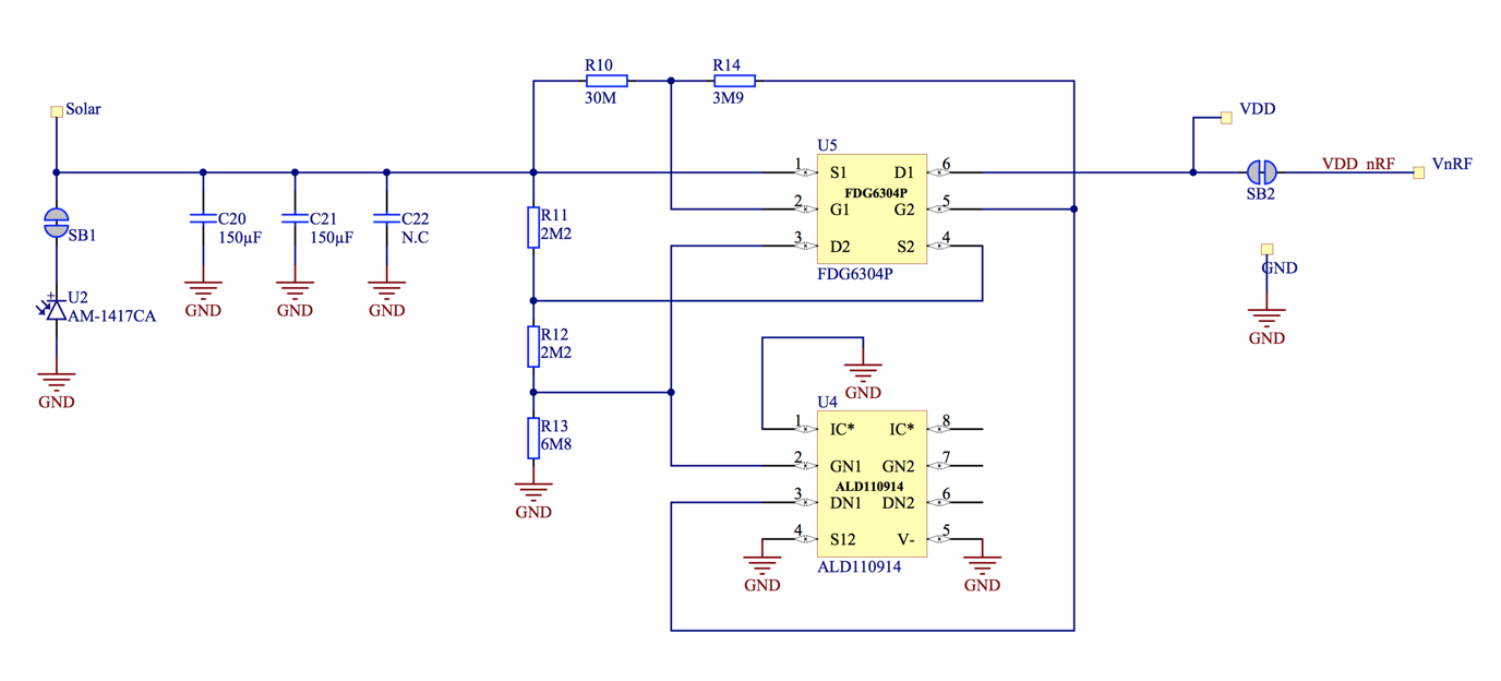
I read through the documentation, but there aren't any notes on adjusting the solar power front end that provides power to the nRF52 is controlled intervals via the four FETs and the resistor divider networks.

We'd like to be able to adjust the solar supply based on the specific solar cell used, or different timing or current requirements ... I don't suppose you happened to have a spreadsheet detailing values used in the reference design to be able to tweak them for different use cases? Or would it be possible to add a quick description of the design choices made on the front end to enable slight modifications?

I don't mind digging into this myself, but figured it was worth asking before I started digging into it. I suspect adding a quick spreadsheet to the hardware download would help a great many people though.

Parents
  • To further clarify, there is some minimal info on the hardware design here: infocenter.nordicsemi.com/index.jsp

    Unfortunately, there are no notes on adjusting the resistor divider values, or any design notes on the specific values chosen, which is unfortunate since this is a particularly inexpensive solution to an interesting problem. A simple spreadsheet in the downloadable hardware folder would help a lot of people out taking a nice design and making some minor changes to it ... or even a quick one or two paragraph explanation of the decisions behind the design with the values and output clearly stated.

    The dual FET ICs and resistor dividers I'm talking about can be seen here:

    Resistor Dividers and FETs

Reply
  • To further clarify, there is some minimal info on the hardware design here: infocenter.nordicsemi.com/index.jsp

    Unfortunately, there are no notes on adjusting the resistor divider values, or any design notes on the specific values chosen, which is unfortunate since this is a particularly inexpensive solution to an interesting problem. A simple spreadsheet in the downloadable hardware folder would help a lot of people out taking a nice design and making some minor changes to it ... or even a quick one or two paragraph explanation of the decisions behind the design with the values and output clearly stated.

    The dual FET ICs and resistor dividers I'm talking about can be seen here:

    Resistor Dividers and FETs

Children
No Data
Related