
Up to this, we've been prototyping with MDBT40 module in our prototypes. We want to move to a completely custom PCB using the nRF51822 SoC for a number of reasons (space and design flexibility being of most concern).
I've already designed and populated the first PCB, and it has really poor RF performance. Data flows fine if I keep the device a few cm from my laptop antenna, but as soon as I move away it starts dropping. I was wondering if anyone could take a look and help me revise it for the next iteration?
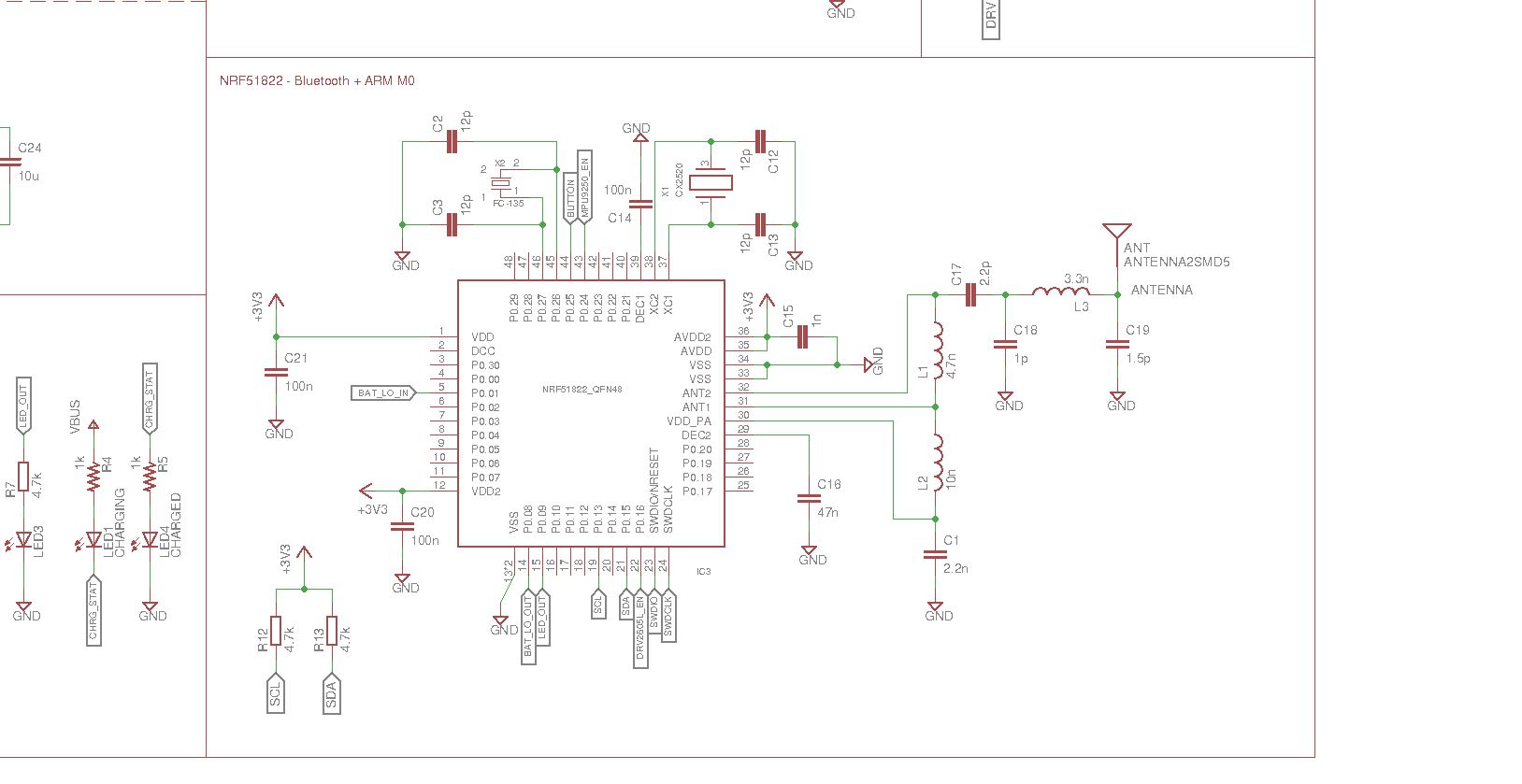
We're using the QFAA variant. The schematic was drawn with reference to the product specification (see page 79). The relevant part of the schematic can be seen below (full resolution).
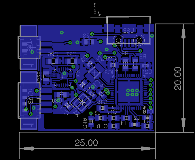
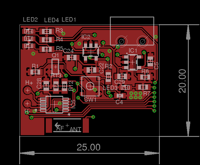
I've included snapshots of the top and bottom layers of the PCB. See below.
This is the antenna used for this design: www.mouser.com/.../ANT-xxx-CHP-x_Data_Guide-11938.pdf
Some notes I've gathered on this problem:
- Poor grounding. The RF network ground has a long way to the SoC ground. There is a keepout below the RF network components. From the product specification, I can see that there is a ground plane below the components, so it should be ok to remove that keepout.
- Antenna spacing. There are traces and ground planes close to the antenna, but no ground plane or traces below it. Is this a problem?
- Tuning. The layout is almost copy-pasted from the product specification. Do I need any external components to tune the antenna?
- Baluns. Would you recommend a single balun chip over seperate components?
And one more thing: From the product specification, looking at sections 11.3, 11.4 and 11.5, the component values for the RF network vary slightly between the 16kB and 32kB RAM variants (QFAA, QFAB and QFAC). Is there a specific reason for this?
Product specification: infocenter.nordicsemi.com/.../nRF51822_PS_v3.1.pdf

