
Hi,
I am programming and debugging an external customised board by following the DK manual and the below link: electronut.in/.../
I use the interface P20 instead of P19, and wire the four signals (VTG, GND_Detect, SWDIO and SWDCLK) to the external board. I think the programming should be fine because I can see the programming processing bar. However, I cannot debug this external board. As mentioned in the manual of DK, the DK should bypass the internal chip and debug the external one if the external one is powered on, but from what I could see, the DK is still debugging the internal chip.
Could you please give me some suggestions? Thanks
[Update]
I checked again about this problem, and I do the following efforts:
-
I first upload a script into the chip, so the chip will print characters on the serial port.
-
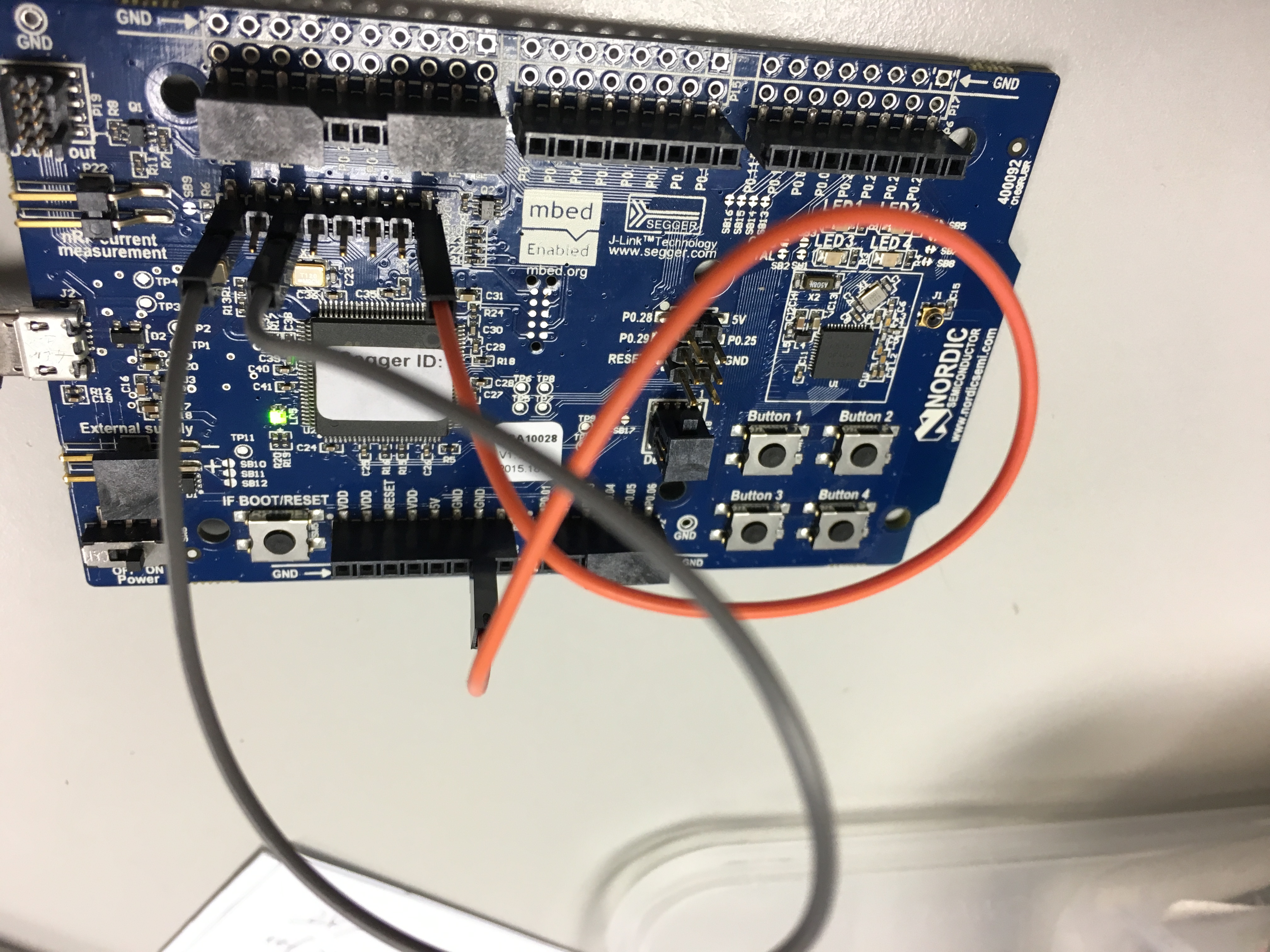
I connect the VDD and SH_VTG of P20, GND and SH_GND_DETECT of P20 together (as the photo show below, without connecting the external board).
-
Under this configuration, I suppose the DK should bypass the internal chip. However, it does not. After powering on the DK, the serial port is still doing the printing.
-
Under this configuration, I tried to do the programming, but it is not successful - meaning the programming is directed to the external chip.
Would you please give me some suggestions?
