
Good morning all,
We have a circuit based on 51822 chip.
We are currently trying to monitor some value from 0v to 24v from the analog inputs. It's working, however, we have found 2 issues.
-
The values we get are between 74 (0V) and 496 (24V) The precise formula is Y = 17,554X + 74,443 with Rquare = 1 where X is the voltage input value and the analog value we get from the chip.
-
Sometimes we need to call the function 2 times in order to get the right analog value for a given voltage. (could it be a buffer problem?)
See image below. I have traced this curve from several measurements.
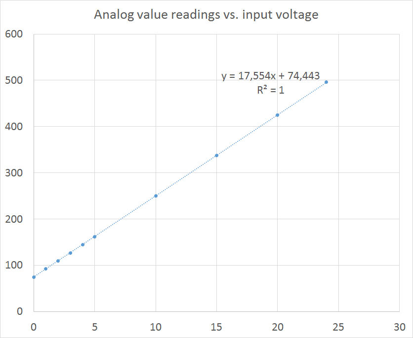
Where this could come from?
To get the 24v down to a reasonable voltage we are using this voltage divider
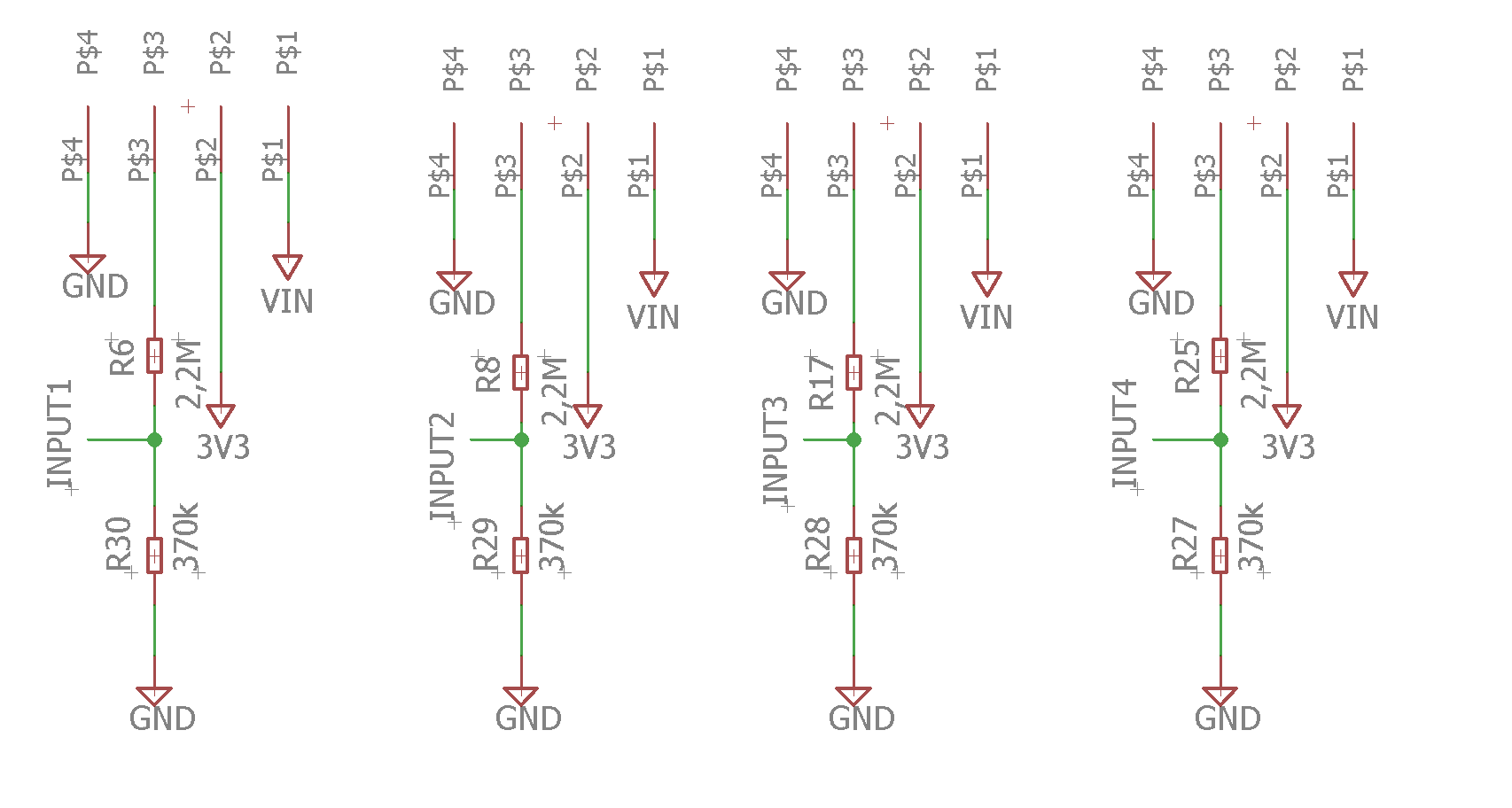 (370k, 2.2M)
To get the value from an input, we are using this formula:
 U16 AINS_GetValue(U8 innum)

 {
  //Clear Event flags
 nrf_adc_conversion_event_clean();

 //Read Sample
 AIns.ADC_Channel[innum].ADC_Buf[AIns.ADC_Channel[innum].State.Bits.Index++] = nrf_adc_result_get();

 //Find average
 AIns.ADC_Channel[innum].ADC_Avg = 0;
 for(U8 i = 0; i < 4; i++) AIns.ADC_Channel[innum].ADC_Avg += AIns.ADC_Channel[innum].ADC_Buf[i];
 AIns.ADC_Channel[innum].ADC_Avg >>= 2;

 //Return value
 return AIns.ADC_Channel[innum].ADC_Avg;

 }
where both functions (nrf_adc_conversion_event_clean(); nrf_adc_result_get(); ) are from the Nordic Semi Ble UART application code.
Could it be my the //Read Sample part of the code the problem?
ADC initialization seems to be OK with the right scaling/resolution/reference but maybe I'm wrong... Inputs # are good since these values are the same for the 4 inputs.
 void AINS_Init(void)
 {
 U32                      pCompareEvent;
 U32                      pADCTask;
 nrf_ppi_channel_t        PPIChannel;
 ret_code_t               error;
 U32                      TimerTicks;
 nrf_adc_config_t         ADCConfig = NRF_ADC_CONFIG_DEFAULT;

 //Initialize AINS structure
 AIns.Current.Number = 0;
 AIns.ADC_Channel[AIN1].hwChannel = AIN1_HWCHN;
 AIns.ADC_Channel[AIN2].hwChannel = AIN2_HWCHN;
 AIns.ADC_Channel[AIN3].hwChannel = AIN3_HWCHN;
 AIns.ADC_Channel[AIN4].hwChannel = AIN4_HWCHN;

 for(U8 i = 0; i < 4; i++)
 {
 AIns.ADC_Channel[i].ADC_Avg = 0;
 AIns.ADC_Channel[i].State.Raw = 0;
 for(U8 j = 0; j < 4; j++) AIns.ADC_Channel[i].ADC_Buf[j] = 0;
 }

 //Initialize PPI
 error = nrf_drv_ppi_init();
 APP_ERROR_CHECK(error);

 //Initialize Timer
 error = nrf_drv_timer_init(&Timer, NULL, Timer_EventHandler);
 APP_ERROR_CHECK(error);

 //Initialize ADC
 ADCConfig.scaling    = NRF_ADC_CONFIG_SCALING_INPUT_ONE_THIRD;
 ADCConfig.resolution = NRF_ADC_CONFIG_RES_10BIT;
 ADCConfig.reference  = NRF_ADC_CONFIG_REF_VBG;
 nrf_adc_configure(&ADCConfig);
 nrf_adc_input_select((nrf_adc_config_input_t)AIns.ADC_Channel[AIns.Current.Number].hwChannel);
 nrf_adc_int_enable(ADC_INTENSET_END_Enabled << ADC_INTENSET_END_Pos);
 sd_nvic_SetPriority(ADC_IRQn, NRF_APP_PRIORITY_LOW);
 sd_nvic_EnableIRQ(ADC_IRQn);

//Configure Timer to generate an event every XX us
TimerTicks = nrf_drv_timer_us_to_ticks(&Timer, AIN_ADC_SAMPLE_PERIOD_US);
nrf_drv_timer_extended_compare(&Timer, NRF_TIMER_CC_CHANNEL0, TimerTicks, NRF_TIMER_SHORT_COMPARE0_CLEAR_MASK, false);

 //Allocate PPI Channel
error = nrf_drv_ppi_channel_alloc(&PPIChannel);
APP_ERROR_CHECK(error);

//Get Event and Task Pionters
pCompareEvent = nrf_drv_timer_event_address_get(&Timer, NRF_TIMER_EVENT_COMPARE0);
pADCTask = (U32)nrf_adc_task_address_get(NRF_ADC_TASK_START);

//Assign and Enable PPI channel
error = nrf_drv_ppi_channel_assign(PPIChannel, pCompareEvent, pADCTask);
APP_ERROR_CHECK(error);
error = nrf_drv_ppi_channel_enable(PPIChannel);
APP_ERROR_CHECK(error);

//Enable timer
nrf_drv_timer_enable(&Timer);
}
Maybe someone see right away what we are doing wrong?
Thanks everyone!
EDIT: Excel file for capacitor calculation CapacitorCalculationforVoltageDivider20160913v1.xls
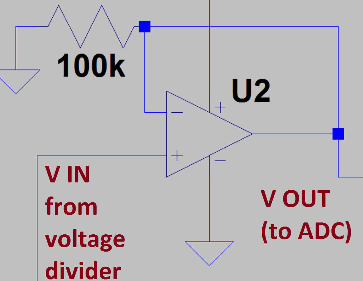
EDIT BIS: OP AMP to isolate ADC
Regards,
Francois
