
I'm working with the PCA10040, the SDK V11.0.0. and the winbond memory flash W25Q80BV.
For the SPI connection I'm using the the SPI2 because TWI0 and TWI1 are being used by other sensors.
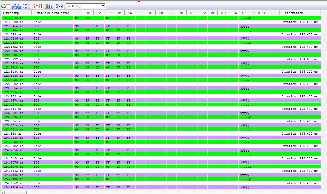
I have a problem when I try to get the memory flash ID information (through order 0x90): It should send (0x00,0x00,0x00,0x00,0xEF,0x13) but instead it sends random values in bytes 5 and 6. I've checked the pin connection of SCK,MISO,MOSI and SS and it's correct. Also I've checked that /HOLD pin is high. I've tried with the 0 and 3 spi modes (as the winbond datasheet indicates) and also different frequencies values, but still I couldn't get the proper value.
Here I attach the code delevoped based on the spi example:
#if defined(BOARD_PCA10036) || defined(BOARD_PCA10040)
#define SPI_CS_PIN   29 /**< SPI CS Pin.*/
#elif defined(BOARD_PCA10028)
#define SPI_CS_PIN   4  /**< SPI CS Pin.*/
#else
#error "Example is not supported on that board."
#endif

#define SPI_INSTANCE  2 /**< SPI instance index. */
static const nrf_drv_spi_t spi = NRF_DRV_SPI_INSTANCE(SPI_INSTANCE);  /**< SPI instance. */
static volatile bool spi_xfer_done;  /**< Flag used to indicate that SPI instance completed the transfer. */

static uint8_t       m_tx_buf= 0x90;           /**< TX buffer. */
static uint8_t       m_rx_buf[6];    /**< RX buffer. */


/**
 * @brief SPI user event handler.
 * @param event
 */
void spi_event_handler(nrf_drv_spi_evt_t const * p_event)
{
    spi_xfer_done = true;
    NRF_LOG_PRINTF(" Transfer completed.\r\n");
}

int main(void)
{
    LEDS_CONFIGURE(BSP_LED_0_MASK);
    LEDS_OFF(BSP_LED_0_MASK);

    APP_ERROR_CHECK(NRF_LOG_INIT());
    NRF_LOG_PRINTF("SPI example\r\n");

    nrf_drv_spi_config_t spi_config = NRF_DRV_SPI_DEFAULT_CONFIG(SPI_INSTANCE);
		spi_config.mode= NRF_DRV_SPI_MODE_0;
    spi_config.ss_pin = SPI_CS_PIN;
		spi_config.frequency= NRF_DRV_SPI_FREQ_1M;
		spi_config.bit_order=NRF_DRV_SPI_BIT_ORDER_MSB_FIRST ;


    APP_ERROR_CHECK(nrf_drv_spi_init(&spi, &spi_config, spi_event_handler));

    while(1)
    {
        // Reset rx buffer and transfer done flag
        memset(m_rx_buf, 0, sizeof(m_rx_buf));
        spi_xfer_done   = false;

        APP_ERROR_CHECK(nrf_drv_spi_transfer(&spi, &m_tx_buf,sizeof(m_tx_buf) , m_rx_buf, sizeof(m_rx_buf)));

        while(spi_xfer_done == false)
        {
            __SEV();
            __WFE();
            __WFE();
        }

						for(int i=0;i<6;i++){
							NRF_LOG_PRINTF(" Received: %04x\r\n",m_rx_buf[i]);
						}

    }
}
Here I attach the RTT information send and the signals values obtained by a logic analyzer.
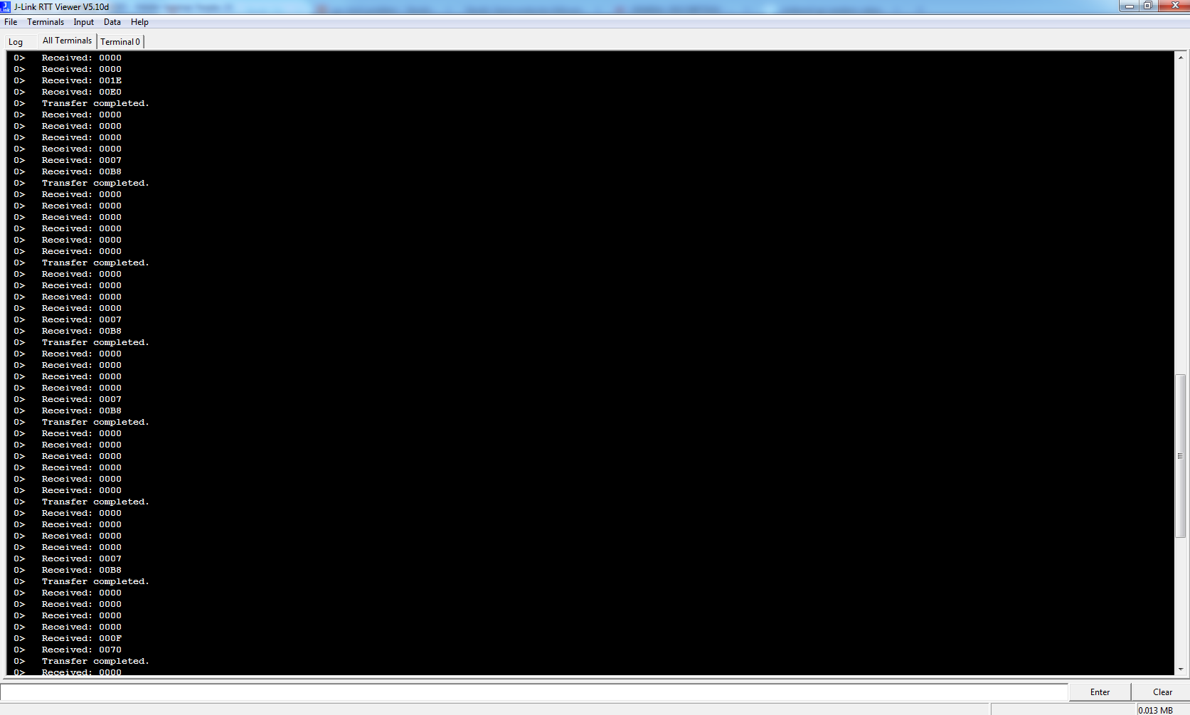
I've tested the memory chip with an arduino application and it's working fine so the problem must be in some configuration parameter of the nordic side.
Somebody has experience a similar issue or have any idea about what I'm doing wrong?
