This post is older than 2 years and might not be relevant anymore
More Info: Consider searching for newer posts

Mystery capacitor C4 in nRF8001 reference balun design

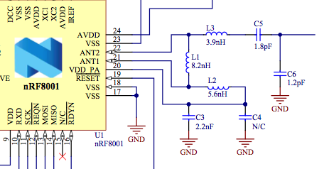
Pages 51 and 53 of the nRF8001 Product Specification (v1.2) show a reference design for a balun network in which capacitor C4 is listed with a value of "N/C". The component list elaborates that this capacitor should not actually be installed.

I'm confused as to why this capacitor is shown at all. Is it important that the PCB be configured with an unoccupied set of pads for some RF-related reason, or is this just a standard balun design which might need C4 in another context but not here?

Can I ignore C4 entirely and redraw the circuit without it?

Balun.png

Parents
  • Hi Garth,

    The reference schematic for our nRF-radios has followed the same "build up" since our first generation of 2.4GHz transceivers. Some of our parts require that you have the C4 populated (pF-range) in order to filter the DC feed to the power amplifier sufficient. However, most of our newer radio cores (nRF24L-series, nRF8000-series, and nRF51-series) does not require this cap. We have removed the mysterious footprint on our nRF51-ref designs.

    The reason why it's still there is because of history. You can safely take away the cap from your design.

    Best regards Håkon

Reply
  • Hi Garth,

    The reference schematic for our nRF-radios has followed the same "build up" since our first generation of 2.4GHz transceivers. Some of our parts require that you have the C4 populated (pF-range) in order to filter the DC feed to the power amplifier sufficient. However, most of our newer radio cores (nRF24L-series, nRF8000-series, and nRF51-series) does not require this cap. We have removed the mysterious footprint on our nRF51-ref designs.

    The reason why it's still there is because of history. You can safely take away the cap from your design.

    Best regards Håkon

Children
No Data
Related