Hello,
My project name is Remote Operated Vehicle. Basically i am using a PS2 controller as the joystick to control the car. So, my aim is to build wireless interface between two microcontroller using nRF24L01. One microcontroller acts as a Tx, and the other one as a Rx. I have already run the code on both microcontroller. But i dont know how to check if there is a successful communication between these two microcontroller. Please help me how do i test this communication? How to check if the Rx gets the message from the Tx? Any help is much appreciated. Thank you!
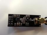
Here is the nRF24L01.. the marking is: NRF A 24L01+ 083DAE Tx code:
/**************************************************************************************************
- Project Name: NRF24L01 demonstration code, Transmitter
- Company: (c) mikroElektronika, 2011
- Revision History:
-
20111104 (ZR): -
- initial release; - Description:
-
This code demonstrates how to use NRF 24L01+ to send and receive data over RF channel. -
It is expected that Rx is setup in such way that it returns ACK as well as 20 bytes of response message (ACK Payload). - Test configuration:
-
MCU: P18F45K22 -
Dev.Board: EasyPIC7 -
www.mikroe.com/.../ -
Modules: NRF24L01+, http://www.nordicsemi.com/ -
ac:NRF24L01P -
Oscillator: 8MHz -
SW: mikroC PRO for PIC -
www.mikroe.com/.../ - NOTES:
-
Both MCU and NRF24L01+ must be powered by 3.3V relative to GND
**************************************************************************************************/
sbit Irq_pin at PORTB.B0; sfr; sbit Mosi_pin at LATC.B7; sfr; sbit Ce_pin at LATA.B4; sfr; sbit Sclk_pin at LATA.B3; sfr; sbit Csn_pin at LATA.B2; sfr; sbit Miso_pin at PORTC.B6; sfr;
sbit Irq_tris at TRISB.B0; sfr; sbit Mosi_tris at TRISC.B7; sfr; sbit Ce_tris at TRISA.B4; sfr; sbit Sclk_tris at TRISA.B3; sfr; sbit Csn_tris at TRISA.B2; sfr; sbit Miso_tris at TRISC.B6; sfr;
char Code_[32]; // addressing code (see datasheet for NRF24L01+) char Outgoing[25]; // outgoing packet char Incoming[25]; // incoming packet
void Init() { ANSELA = 0; ANSELB = 0; ANSELC = 0; ANSELD = 0; LATD = 1; TRISD = 0;
INTCON = 0; // disable all interrupts
// address code Code_[10] = 0xAA; // choose bytes at your wish Code_[11] = 0xAA; Code_[12] = 0xAA; Code_[13] = 0xAA; Code_[14] = 0xAA;
NRF24L01P_RF_Channel = 20; // Radio frequency channel, in range 0..124 NRF24L01P_Init(5); // initialize NRF24L01+ NRF24L01P_Setup_Tx(Code_); }
void MakeMessage() { // form outgoing message char i; for (i = 0; i < 20; i++) { OutGoing[i] = i; } }
char DoRF() { char i; char result;
MakeMessage(); result = 0; // no receiver in range while (result != 255) { // keep trying until receiver gets the message memset(&incoming, 33, 20); // prepare incoming i = NRF24L01P_Send(OutGoing, Incoming); // Call receiver Delay_100ms(); LATD++; // indicate that Tx is in progress if (i == 0) { // Rx has received the message and returned the answer, which is in the "Incoming" array LATD = 0; // process Incoming array to extract the message from Rx result = 255; // All is OK, the receiver has got the message } else { // Rx did not receive the message } } }
void Main() { Init; while (1) // keep on transmitting DoRF(); }
Rx code:
/**************************************************************************************************
- Project Name: NRF24L01 demonstration code, Receiver
- Company: (c) mikroElektronika, 2011
- Revision History:
-
20111104 (ZR): -
- initial release; - Description:
-
This code demonstrates how to use NRF 24L01+ to send and receive data over RF channel. -
The reciver is setup in such way that it returns ACK as well as 20 bytes of response message (ACK Payload). - Test configuration:
-
MCU: P18F45K22 -
Dev.Board: EasyPIC7 -
www.mikroe.com/.../ -
Modules: NRF24L01+, http://www.nordicsemi.com/ -
ac:nrf24L01p -
Oscillator: 8MHz -
SW: mikroC for PIC -
www.mikroe.com/.../ - NOTES:
-
Both MCU and NRF24L01+ must be powered by 3.3V relative to GND
**************************************************************************************************/
char InData[25]; // incoming data from RF char testRcv; char PayLoadBuff[25]; char Code_[32];
sbit Irq_pin at PORTB.B0; sfr; sbit Mosi_pin at LATC.B7; sfr; sbit Ce_pin at LATA.B4; sfr; sbit Sclk_pin at LATA.B3; sfr; sbit Csn_pin at LATA.B2; sfr; sbit Miso_pin at PORTC.B6; sfr;
sbit Irq_tris at TRISB.B0; sfr; sbit Mosi_tris at TRISC.B7; sfr; sbit Ce_tris at TRISA.B4; sfr; sbit Sclk_tris at TRISA.B3; sfr; sbit Csn_tris at TRISA.B2; sfr; sbit Miso_tris at TRISC.B6; sfr;
void interrupt() { // in case you use interrupts, here is the moment when Rx has got the data from Tx
//**************** Rx interrupt ******************* if (INTCON.INT0IF == 1) { INTCON.INT0IF = 0; // clear interrupt flag on RB0 (IRQ pin) } //************************************************* }
void PreparePayload() { char i; // prepare payload to be sent together with the ACK (see datasheet for NRF24L01+) for (i = 0; i < 20; i++) PayLoadBuff[i] = i; NRF24L01P_Write_Ack_Payload(PayLoadBuff, 0); // store payload to transmit buffer }
void Init() { ANSELA = 0; // all pins digital ANSELB = 0; ANSELC = 0; ANSELD = 0;
LATD = 1; TRISD = 0; // we will use PORTD for indicators
INTCON = 0; // no interrupts
INTCON.INT0IE = 1; // allow interrupt on INTO (IRQ_PIN) INTCON2.INTEDG0 = 0; // falling edge on INT0 causes the interrupt
RBPU_bit = 0; // enable weak pull up on PORTB
memset(&InData, 0, 21);// clear the array
Code_[10] = 0xAA; // address code, must be the same on Rx and Tx side Code_[11] = 0xAA; Code_[12] = 0xAA; Code_[13] = 0xAA; Code_[14] = 0xAA;
INTCON.GIE = 1; // enable all interrupts, if you want them }
char DetectTx() { char passcnt; char result;
passcnt = 0; result = 0; NRF24L01P_PowerUp(); // start the NRF chip NRF24L01P_Rf_Channel = 20; // set the radio channel, from 0..124 NRF24L01P_init(5); // initialize RF module with the highest power NRF24L01P_Setup_Receiver(Code_); // configure receiver memset(&InData, 0, 21); testRcv = NRF24L01P_Receive(InData); // procitaj ako je ista je stiglo na RF- brisi buffer PreparePayload(); NRF24L01P_ClearIRQ();
while (1) { passcnt = 0; // try 50 times before giving up while (passcnt < 50) { if (NRF24L01P_Has_Data()) { // is there any data received? testRcv = NRF24L01P_Receive(InData); // read the data and clear Rx buffer PreparePayload(); // prepare payload for the next session passcnt = 0; LATD ++ ; // show activity when data arrives result = 1; } passcnt++; Delay_100ms(); }
  NRF24L01P_PowerDown();            // shut down NRF24L01+
  Delay_100ms();
  NRF24L01P_Rf_Channel = 20;       // working channel
  NRF24L01P_Init(5);                // Initialize RF module
  NRF24L01P_Setup_Receiver(Code_);  // Reinitialize receiver
  memset(&InData, 0, 21);           // Clear inoming buffer
  LATD.B7 = PORTD.B7 ^ 1;
  PreparePayload();                 // prepare payload for the next session
  if (testRcv)
  {
      // the data has been received
      result = 1;
  }
} }
void main() { Init();
while (1) { if (DetectTx()) { // Tx is here, the data is received, it is stored in InData memset(&InData, 0, 21); // clear indata } } }
I donwloaded the code from libstock.