This post is older than 2 years and might not be relevant anymore
More Info: Consider searching for newer posts
This discussion has been locked.
You can no longer post new replies to this discussion. If you have a question you can start a new discussion

GPIO high drive on nRF52, any limitations?

I have a rather unique problem. I want to control an "old-fashioned" DPDT relay using nRF52 GPIO lines. I'm trying to accomplish this task without adding a power transistor circuit to my design. (My prototype board is already a mess of solder puddles, and I'm also running out of room.)

The relay specs state that a nominal voltage of 1.5V, and a nominal power of 50 mW, are required to operate the coil. I've also read that it's possible to damage a coil with too much power. So I have proceeded cautiously. A single GPIO line at standard drive strength gave me only 0.35 V across the coil. Obviously, that wasn't enough to operate it. Switching to high drive strength gave me 1.35 V. I still did not see the relay operate.

I wired two GPIO lines together, set them both to high drive strength, and operated them in tandem. The relay is still not operating, but I'm up to 1.95 V across the coil.

Since I'm over the nominal voltage for the relay, I speculated that I'm still not sourcing enough current. At 1.95 V, I need 26 mA to achieve 50 mW. But this diagram from the nRF52 data sheet suggests that I should have enough power:

image description

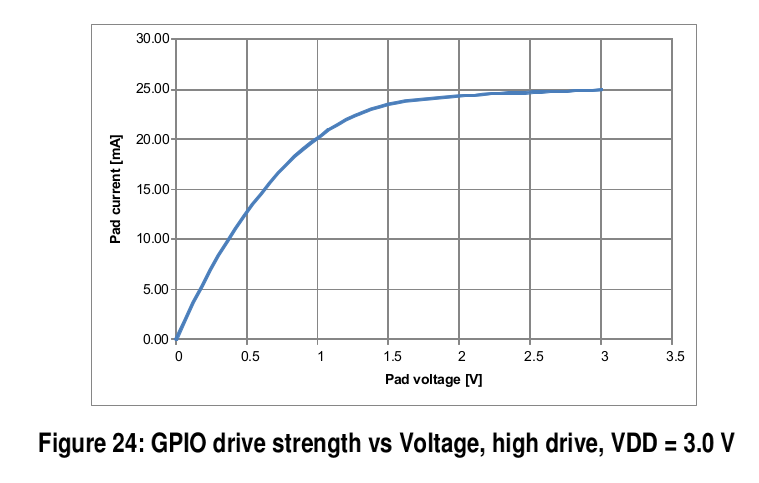
At 1.95 V, EACH of my high-drive GPIO lines should be able to source around 22 mA. I should therefore have 44 mA, and 86 mW.

I came across a discussion which states that the nRF51 can only have three high drive strength GPIO lines. I haven't seen anything similar in the documentation for the nRF52, or in any discussions here in the Developer Zone. What do I need to know?

Thanks for any advice and guidance.

  • Hi,

    You should use a MOSFET transistor. A SOT-23 transistor does not take much space. Driving a relay directly from the gpio pin will drive the gpio pin out of spec when it comes to current. We recommend 15mA total max current on the nRF52 gpio pins. This can be on one pin if you want. If you go outside this we cannot guarantee the stability of the device. We also recommend that you sink current rather than source, because there are more ground pads on the device than VDD pads.

    Regarding the figure, you are reading it the other way. This figure tells you the pad voltage when you are sinking current. If you sink 25mA the pad voltage will be 3V, as 25mA is the absolute maximum current you can sink from a pin. If you want 2V on the pin you can sink 20mA, but again this is not recommended, especially when doing this on two pins.

    Here is a related case discussing nRF52 max gpio current: devzone.nordicsemi.com/.../.

    You will have to make room for that transistor. And also don't forget to add a flyback diode across the relay input.

  • Thank you Mr. Bauck, that was very helpful information.

    It would appear that the nRF52 actually has a lower current driving limit than the nRF51. That's fine, I'm sure most people don't need much current driving capability, and it can always be added.

    A few weeks ago while I was waiting for your reply, I found some NPN transistors to drive the relay. It appears that I need two of them, since the relay is a latching type. I tried to drive those transistors with GPIO. But I didn't have flyback diodes in my first circuit. And it appears that I actually damaged an nRF52 DK board with this circuit. Oops. Live and learn.

Related