This post is older than 2 years and might not be relevant anymore
More Info: Consider searching for newer posts

PCA10000 using with another PCB stack

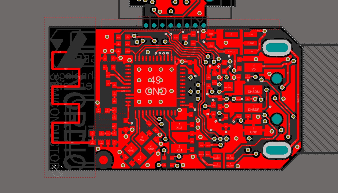
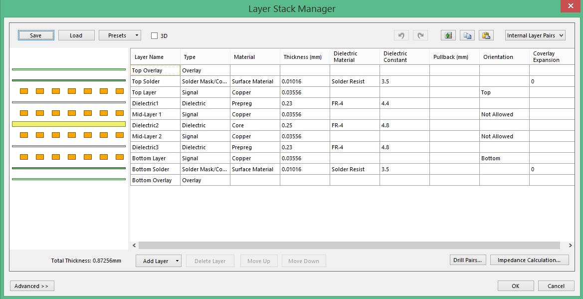
Hello! I am designing PCA10000 based PCB. Unfortunately my manufacturer can't make PCB using prepegs and cores that used in PCA10000 (4.4 and 4.8). They can make using 4.6 core and 3.9 prepreg. So, it seems I need redesign PCB project? What is the best way to do that without loosing antenna performance? I tried to simulate PCA10000 pcb + antenna using Ansys HFSS:

image description

image description

image description

image description

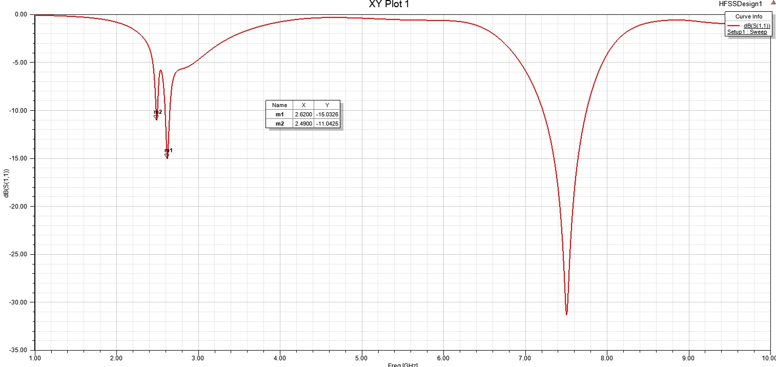
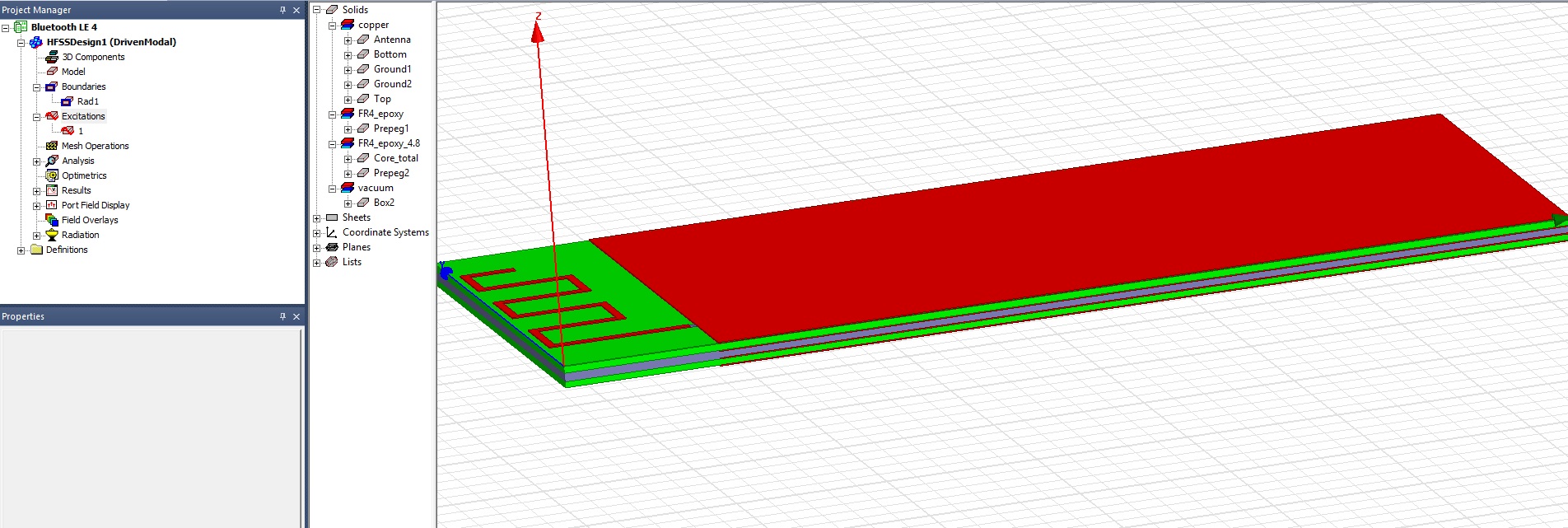
Here is HFSS project: cloud.mail.ru/.../Txe2ouz4d My simulation result shows me that there is two resonating frequencies: 2.49 GHz and 2.62 GHz. Could someone advise me does it is a mistake? Should I now simulate a pcb with available dielectric constant? Which frequency should be the reference point?

Also I can't understand why impedance of antenna is 64 OHm and not 50 OHm? I get that using trace width = 0.256mm, Trace Thickness = 0.03556, Substrate Height = 0.23 mm and Substrate Dielectric = 4.4.

  • FormerMember
    0 FormerMember

    The reference layout was made so that it should be independent of the stack-up. As you can see on PCA10000 (nRF51), the ground layer used for the chip and the matching network is the bottom layer. The reason is that when using a discrete matching network for the chip, there needs to be a distance between the chip/matching network and ground. With the stack-up used on PCA10000, the distance between layer 1 and layer 2 is very short. If using layer 2 as the ground layer it will affect the radio because of parasitic capacitance and result in lower output power.

    Therefore, in your case, you should just copy the reference layout, and make sure to have some distance between the chip/matching network and ground. Also, under the matching network there should be ground. It means that the inner layers in that region should have a keep-out region under the matching network.

    The antenna has a matching network (C14, R17,L4). The values of the matching network components were found during tuning to make the impedance of the antenna 50 Ohm.

Related