This post is older than 2 years and might not be relevant anymore
More Info: Consider searching for newer posts

Nrf51422-QFAA with BAL-NRF01D3

Hello, I am developing a board, with nrf51422-qfaa chip. To match the antenna I'm using the BAL-NRF01D3 balun. I currently have problems with antenna not working and I'm trying to "debug" the hardware. I discovered that my antenna trace is shorted to ground. Is it perhaps caused by the balun inner structure? For example, a coil going from antenna trace to ground that is not a shortage for RF frequencies? I'm not sure whether my balun is correctly soldered so I'm trying to narrow the search for the fault.

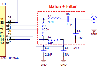
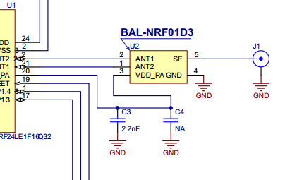
Below I attached pictures from ST datasheet and it seems that a capacitor is between J1 (antenna) trace and ground, but I'm not sure.

image description image description

  • FormerMember
    0 FormerMember

    It should work fine to use a balun. But, as you know, it is very small, so one have to be very careful to avoid any short.

    Also, what does your layout look like, is it a copy of the reference layout? It is very important to copy the RF part of the reference layout. It means that there should be a lot of ground, and the distances in your layout should be the same as in our reference layout.

    Do you have a long transmission line towards the antenna? If so, it's important to make sure that the transmission line is a 50 Ohm transmission line (coplanar waveguide).

  • Thank you for the answer! It finally worked, but the fault was very trivial. The 16 MHz oscillator footprint was mirrored, so after soldering in correct position (rotated 90 deegrees) everything worked. I'm pleasantly surprised that the bluetooth signal power shown in nrf Master Control Panel is around -32 dBm. From the app running on the dev-board I got around -60 dBms ;)

Related