I have the PPK measuring a custom nRF52-based board. The board consists of the nRF52, a I2C sensor, and bunch of caps (210uF worth). We built a custom board to do current measurement (this was before the PPK was released). The custom board does essentially what the PPK does, except it uses a scope for the UI instead of a PC application.
According to my calculations from the nRF52 spec sheet, our board should be drawing a peak current of 6mA when the radio transmits at 0dBm (5.3 spec'd with DC-DC enabled rounded up). Our custom current measurement board is reporting 5.6mA peak current draw. The PPK is reporting 15mA to 25mA. That's a pretty big discrepancy.
If I load the nRF52 DK with essentially the same firmware (sensor code removed), the PPK reports a much more believable 8mA peak current draw.
But here's the fun part: the average current reported by the custom current measurement board and the PPK match up within a few hundred nA when measuring the nRF52-based board and the nRF52 on the development kit. The PPK is reporting 14.5uA average. The custom current measurement is reporting 14.8uA average.
Hopefully that makes sense.
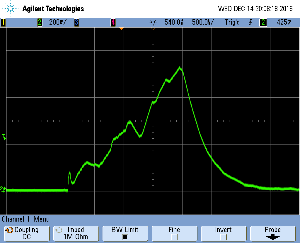
Here's a screen shot of the peaks.
Here's what the scope is seeing with our current sense board (all analog). The scale is 200mV / mA. The peak is typically in the 1.06V range, which means peak current draw is 5.3mA (1060mV / 200mV). There are a lot of caps on the DUT, which is why the waveform is smooth. I'm not super concerned over the peak current not getting accurately reported. I have a sneaking suspicion the device under test is causing some oscillations on the PPK, because the same FW loaded onto the nRF52 DK reports accurate peaks current.