This post is older than 2 years and might not be relevant anymore
More Info: Consider searching for newer posts

INPUT 0.3VDD--0.7VDD

image description

image description Dear all,

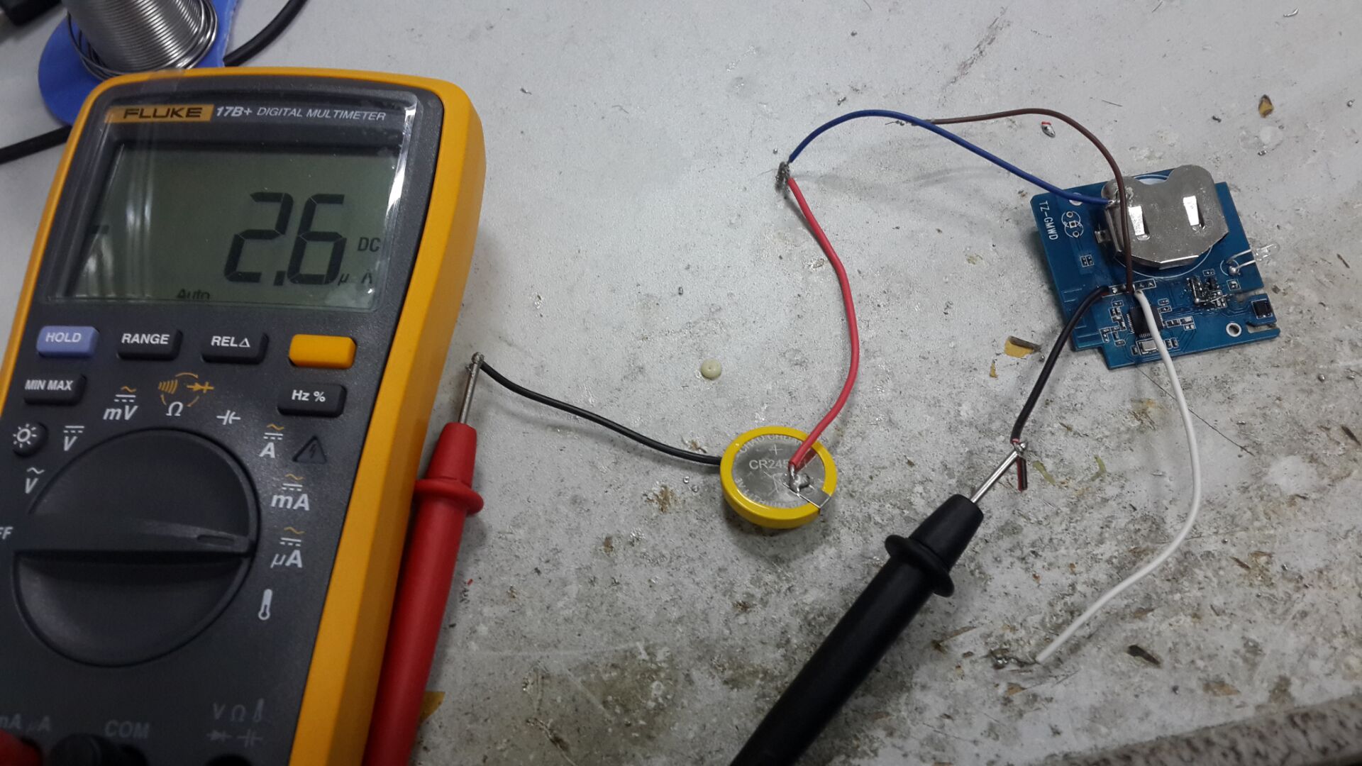
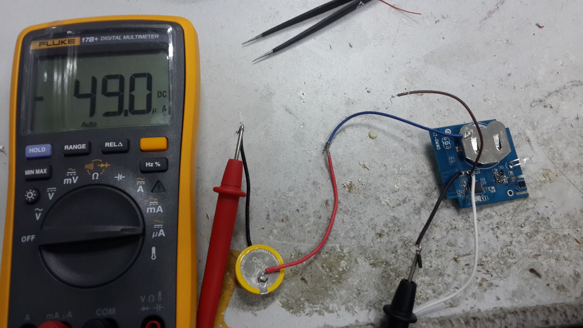
i configure pin 3 to float input.when the pin3 input 0.3VDD--0.7VDD,the chip current have 25--400ua,other is normal(4ua) Why?

SDK:8.1.0 s110

      #define PHOTO_PIN_NUMBER					3	
      nrf_gpio_cfg_input(PHOTO_PIN_NUMBER,NRF_GPIO_PIN_NOPULL);
Parents
  • I tried here, but didn't see the issue.

    It doesn't make much sense on why setting a pin as input should cause extra current.

    I suggest to test on a pin that doesn't connect to anything. You can try to switch the pin configuration from input to disconnected (disable input buffer), say every second and observe if the current consumption change accordingly every second or not.

    Also what would be the behaviour if you use pull up or pull down ?

    you may want to provide the schematic of your board. I don't understand what is R1 and R2 for, what is Vr2.

Reply
  • I tried here, but didn't see the issue.

    It doesn't make much sense on why setting a pin as input should cause extra current.

    I suggest to test on a pin that doesn't connect to anything. You can try to switch the pin configuration from input to disconnected (disable input buffer), say every second and observe if the current consumption change accordingly every second or not.

    Also what would be the behaviour if you use pull up or pull down ?

    you may want to provide the schematic of your board. I don't understand what is R1 and R2 for, what is Vr2.

Children
No Data
Related