This post is older than 2 years and might not be relevant anymore
More Info: Consider searching for newer posts

Is this a reasonable/acceptable antenna tuning for nrf52832?

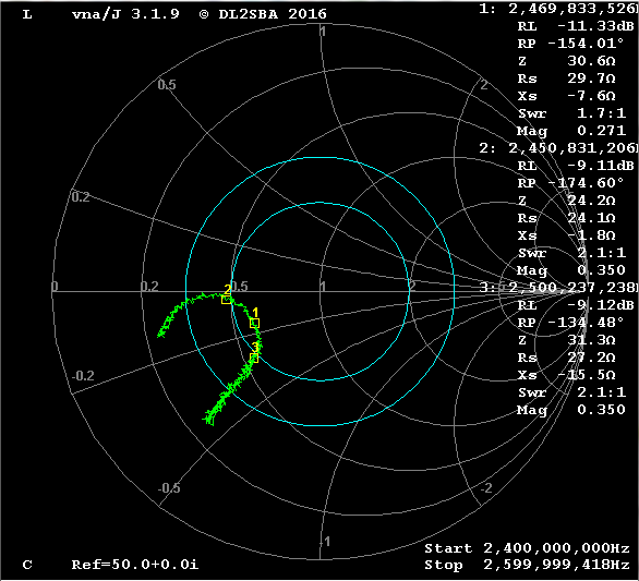
I'm trying to tune a chip antenna for nrf52832. I am not an RF engineer but have figured out how to get the basic VNA measurements done. I've been fighting with finding caps and inductors to get as close as possible to the 50 Ohm 2.45GHz center freq', but this is the best I managed to get:

image description(/attachment/c49d4d14fd28120a0e54c6bcf194c288)

image description

image description

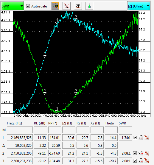
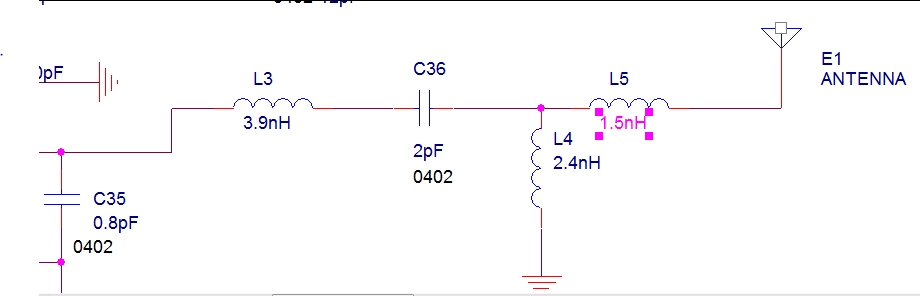
Is this considered a reasonable tuning? In the white paper, the recommendation was SWR<2. I couldn't get the impedance to go any higher than ~30 Ohm. The circuit is based on the solar beacon reference design.

Any tips or recommendations on how to improve this are more than welcome!

  • With a return loss of around 9 dB, you will not be able to gain much by extra performance by further optimization. The way I optimize matching is by measuring the antenna with a VNA, then modeling it as an equivalent R/C or R/L combination and putting it in RFsim99. Then you can use the autotuning capabilities of this program to calculate the matching components. You could verify performance by measuring at the 50 Ohm point in your circuit (probably at the same spot as you do now) The real problem is measuring the antenna alone, but in the enclosure. You need to understand the concept of the reference plane of your VNA measurement. Transmission lines (pcb traces) must also be included in the simulation. If you are not an RF engineer (even if you are), it is easy to be fooled by a VNA. Every mm of extra length in traces, connectors etc will change the Smith chart and the needed compensation. Be aware the the cable you use to connect the antenna to the VNA will look like a part of the antenna. Most antennas need a ground plane at least the size of 1/4 wavelength. If your pcb is smaller, the cable to the VNA will act as ground. Some ferrite beads may block radiation from the cable. Welcome to the world of RF measurement technology...

  • Thank you for this feedback. You write "With a return loss of around 9 dB, you will not be able to gain much by extra performance by further optimization." Can you elaborate? Does that mean I won't be able to match it at 50 ohm?

    It would really help if you can reference a guide/white paper on how to run such simulation on RFsim99?

    Thank you! Shay

  • For a transmitter, if there is an impedance mismatch, part of the generated signal will be reflected back to the transmitter instead of being radiated by the antenna. The return loss is equal to the level of the reflected signal (normalized to the transmitted level). Let's take a return loss of 10dB, that's easier to calculate and very close to your measurement. If you generate 0 dBm, then -10 dBm is not radiated. That is 10% not radiated, so 90% gets radiated. That is equivalent of a loss of 0.5 dB. Your receiver will see a 0.5 dB lower RSSI, that is usually insignificant. RFsim99 is easy to use, there are probably tutorials online or on youtube.

  • Thank you Reinier for those comments. I have another short question - what is the recommended center frequency and what is considered a reasonable deviation from it?

  • You should aim at a return loss of 10 dB over the complete BLE frequency range of 2402 to 2480 MHz. So the center frequency is 2441 MHz. I now see your frequency range is too limited, I assumed you had the markers at the band edges.

Related