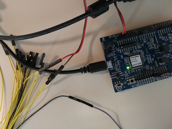
I am using PCA10040 evaluation board to test I2C connection.
I tried twi_scanner sample code in SDK 12.
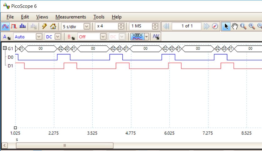
I wired SCL and SDA pins to D0 and D1 to a PicoScope device.
When the code was running, I captured signals from those two pins.
The clock and data lines are completely wrong, right?
- The clock cycles are far below expected: at least 8 for for one write, isn't it?
- Data line should start before clock line; but in my capture, they started to fall at almost the same time.
Can anyone explain why?
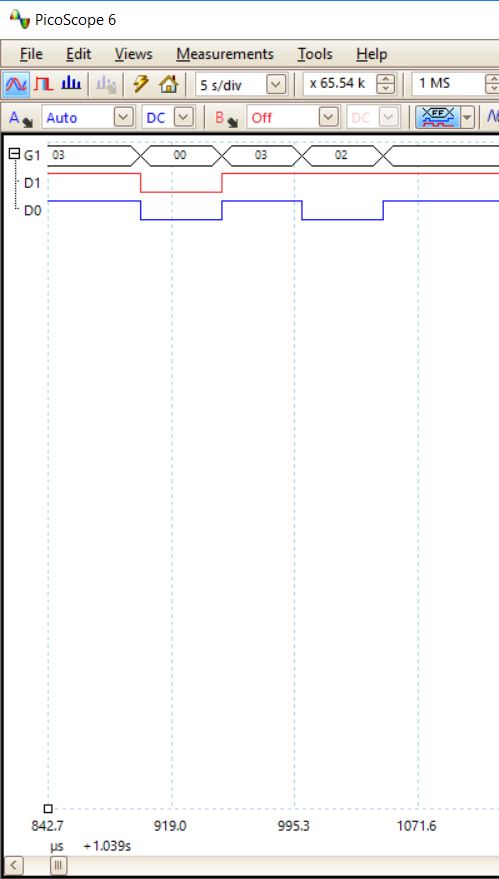
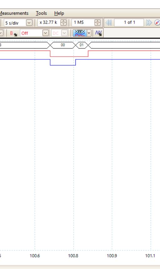
I also did another test with the following code:
int main(void) { nrf_gpio_cfg_output(ARDUINO_SCL_PIN); nrf_gpio_cfg_output(ARDUINO_SDA_PIN);
  for (address = 1; address <= TWI_ADDRESSES; address++)
  {
	nrf_gpio_pin_set(ARDUINO_SDA_PIN);
	nrf_delay_ms(200);
	nrf_gpio_pin_set(ARDUINO_SCL_PIN);
	nrf_delay_ms(200);
	nrf_gpio_pin_clear(ARDUINO_SDA_PIN);
	nrf_delay_ms(200);
	nrf_gpio_pin_clear(ARDUINO_SCL_PIN);
	nrf_delay_ms(1000);
 }
}
The captured two pins signals are as good as expected, which means my way of the signal monitoring is correct, unless for I2C wiring there are special settings I missed.