This post is older than 2 years and might not be relevant anymore
More Info: Consider searching for newer posts

Problem with radio frequency custom board. Balun mismatch?

Hi Nordic,

I have an application that perfectly runs in the nrf51DK but that does not work in my custom board. In my custom board everything else works (i2c, leds lighting, etc..) except for the communication related stuff. I think I am having some problems with the antenna. The balun I am using is 2450BM08B0003, which is the one recommended in this page for the nrf51422. As a detail, the components in the board have been placed by hand and soldered with oven reflow.

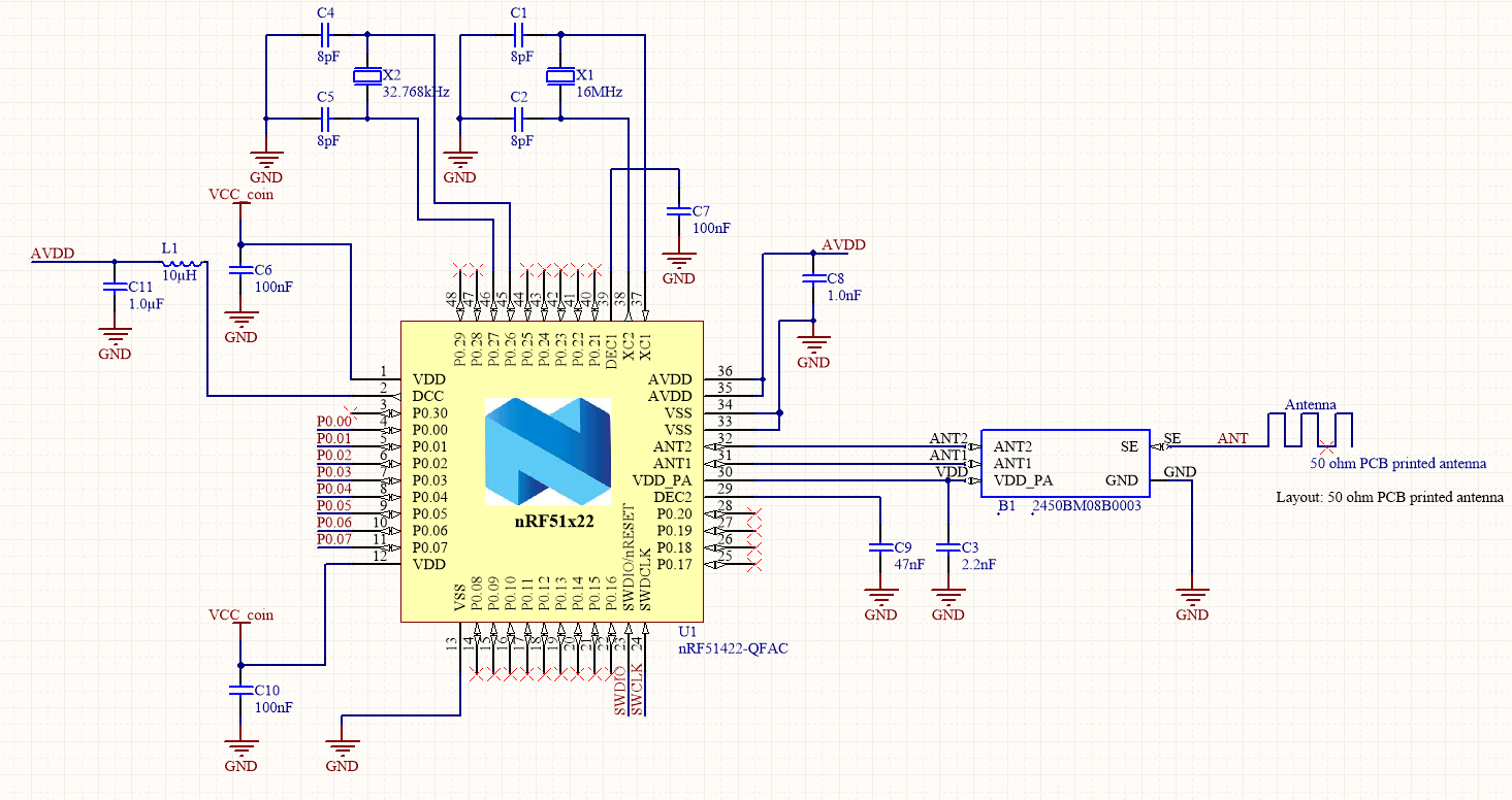
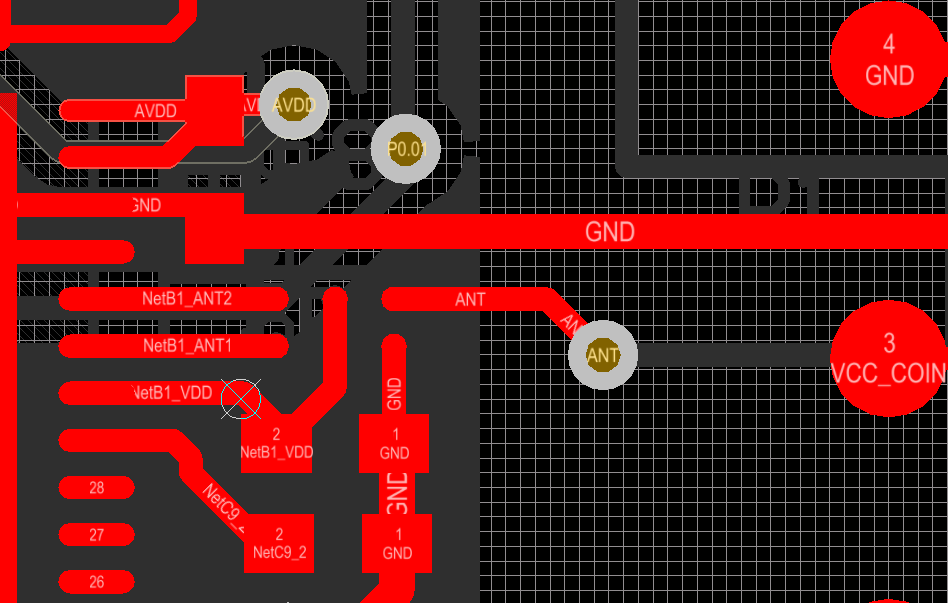
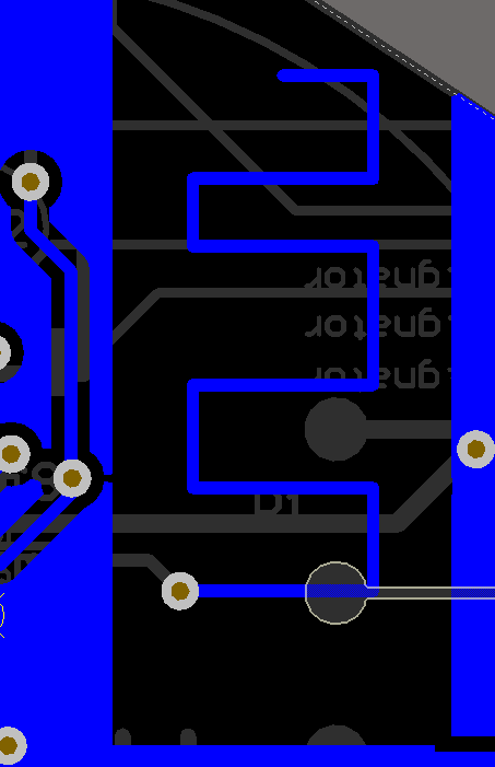
Here I attach the parts of the design that have to do with the communication.

image description

image description

image description

Any idea on how to debug my problem? I have no idea what is going on. I have been reading some other people have the exact same problem, but I have yet no idea of a proper solution.

PS: Sometimes we can transmit data from our custom board to the nordic developer kit. But not the other way around, we cannot receive data. Is this usual?

Thanks for your help!

Parents
  • Hi Angel, Michael has a lot of good points regarding the antenna. To sum it up:

    • There should not be any signal traces beneath the antenna.
    • There are no tuning components for the antenna. (this is increasingly important with a via in the RF path.
    • The antenna must be tuned using a network analyzer for optimum performance. This is hard without any tuning components though.

    In addition I have some comments:

    • The balun you are using is designed for the WLCSP package version, and thus transforms the load impedance into a different one than the QFN package version requires for optimum performance. The correct Johanson part would be 2450BM14E0003 in your case.
    • This particular antenna is a meander antenna design, which relies on the geometry in order to radiate. The total length is not relevant as in a monopole antenna. It looks very much like an antenna which we have been using in a lot of our designs, but one of the sides is too short, which will decrease the radiation efficiency.
    • The antenna should be placed on the end of the board, not in the middle. Ideally (for this one at least) there should be free space on three sides, and a ground plane on the feed side.
    • The balun is not properly grounded, there should be a larger land with multiple vias to bottom/internal ground planes around the ground solder pad. The balun seems to be placed approximately the correct distance from the nRF though.
    • There is a 15 nH inductor missing between L1 and C11 for filtering noise from the DCDC converter.

    As Michael said you might be better off redoing the layout. Prioritize the antenna and radio placement, place it where it will radiate freely, and where it is free from metal objects and e.g. not covered by a hand when used. Also, if you did not already, check out the nRF51 PCB design tutorial and the reference design with Johanson balun, which also contains Altium designer files that you can use. Using the nRF51-Dongle HW files you can also see how to use the nRF51 with this kind of antenna, however with a discrete component matching network.

    And as always, please feel free to submit your design for review before shipping it off to production.

  • Hi Angel, Good to hear.

    While the correct balun might be easier to solder, having the solder pads on the side instead of on the bottom, it should be a little too wide for your current footprint. You might be able to fit it by making solder bridges or something, with some degradation in performance.

    The noise due to the missing 15 nH should be easy to spot if you get a signal out, but you need a spectrum analyzer. Set up a TX carrier and look for spurious that pop up when you enable the DCDC converter.

    The 16 MHz XOSC is only needed for a few modules, if not the internal 16 MHz RC oscillator will be requested. Still it might be incorrectly loaded. Timing is generally depending on the LF CLK though, you could try to simply change LF CLK source to either internal RC or synthesized from HFCLK.

Reply
  • Hi Angel, Good to hear.

    While the correct balun might be easier to solder, having the solder pads on the side instead of on the bottom, it should be a little too wide for your current footprint. You might be able to fit it by making solder bridges or something, with some degradation in performance.

    The noise due to the missing 15 nH should be easy to spot if you get a signal out, but you need a spectrum analyzer. Set up a TX carrier and look for spurious that pop up when you enable the DCDC converter.

    The 16 MHz XOSC is only needed for a few modules, if not the internal 16 MHz RC oscillator will be requested. Still it might be incorrectly loaded. Timing is generally depending on the LF CLK though, you could try to simply change LF CLK source to either internal RC or synthesized from HFCLK.

Children
No Data
Related