This post is older than 2 years and might not be relevant anymore
More Info: Consider searching for newer posts

Counter does not count correctly external signal

Hello, I'm having special SPI protocol which requires SPI Slave to toggle REDAY pin after every byte. I do test using 2 nRF52 boards. One is SPI master, another is slave. When I do it in SW then it works fine for multiple hours. There is a loop that SPI is set to receive 1B, then SW toggles RDY, then SPI is set again to receive 1B... But when I wanted to optimize and let HW count SPI_CLK and generate RDY it start to be unstable. It usually stops working within 3 minutes. With Saleae logic analyzer I discovered that READY pin is toggled one falling edge sooner.

The HW configuration is as follows:

  • I use in parallel my SPI_CLK with GPIOTE module. Falling edge is set to generate an EVENT.
  • Event is connected via PPI into COUNTER.
  • counter compare register CC[0] is set to 8 (falling edges).
  • Another PPI connects Counter COMPARE event into REDAY GPIOTE toggle.

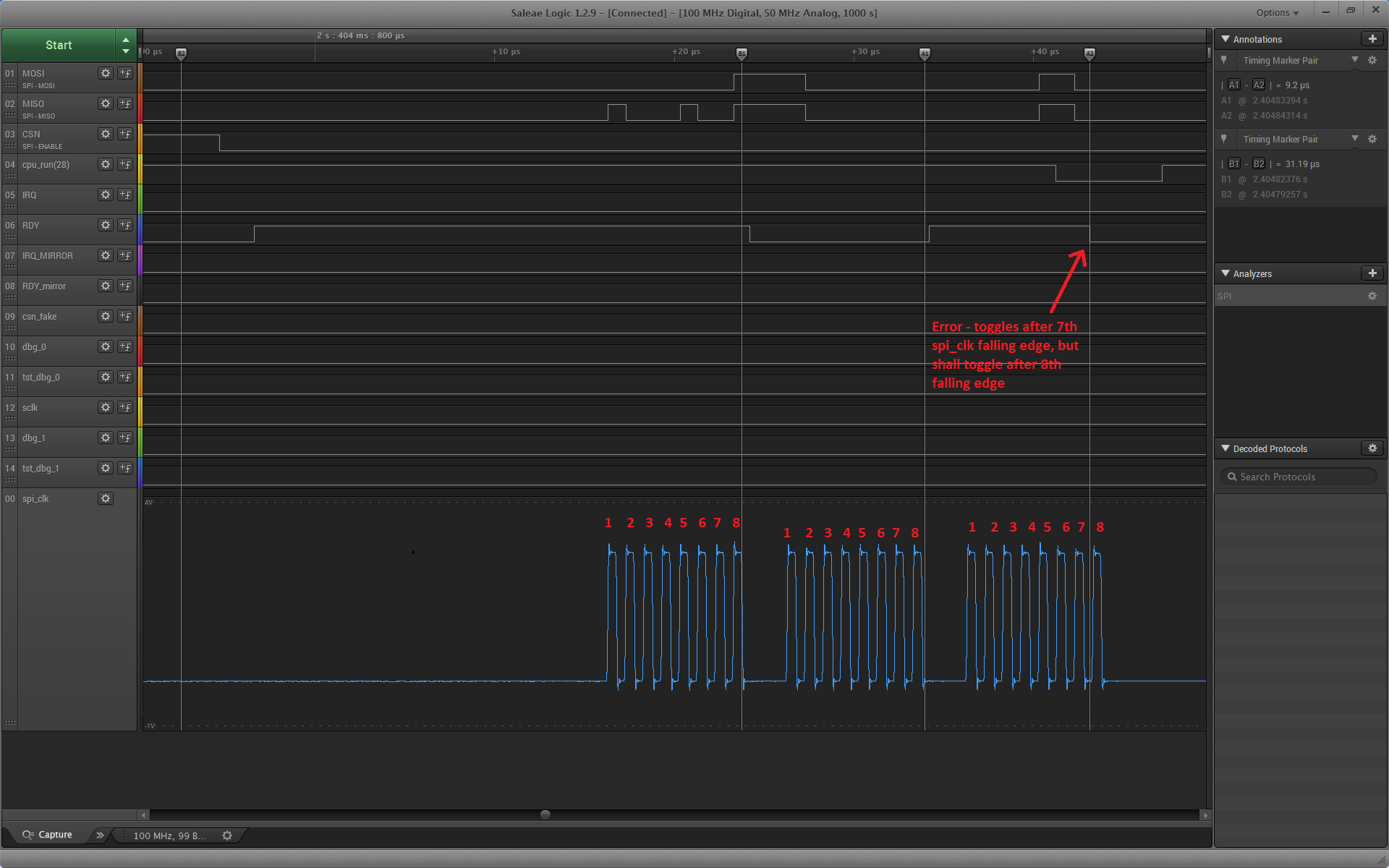
In bellow screenshot is seen that it works for first 2B but on 3rd byte RDI triggers after 7th edge. Do you know what is wrong and how can I workaround it?

image description

[EDIT 25.1.2017] 
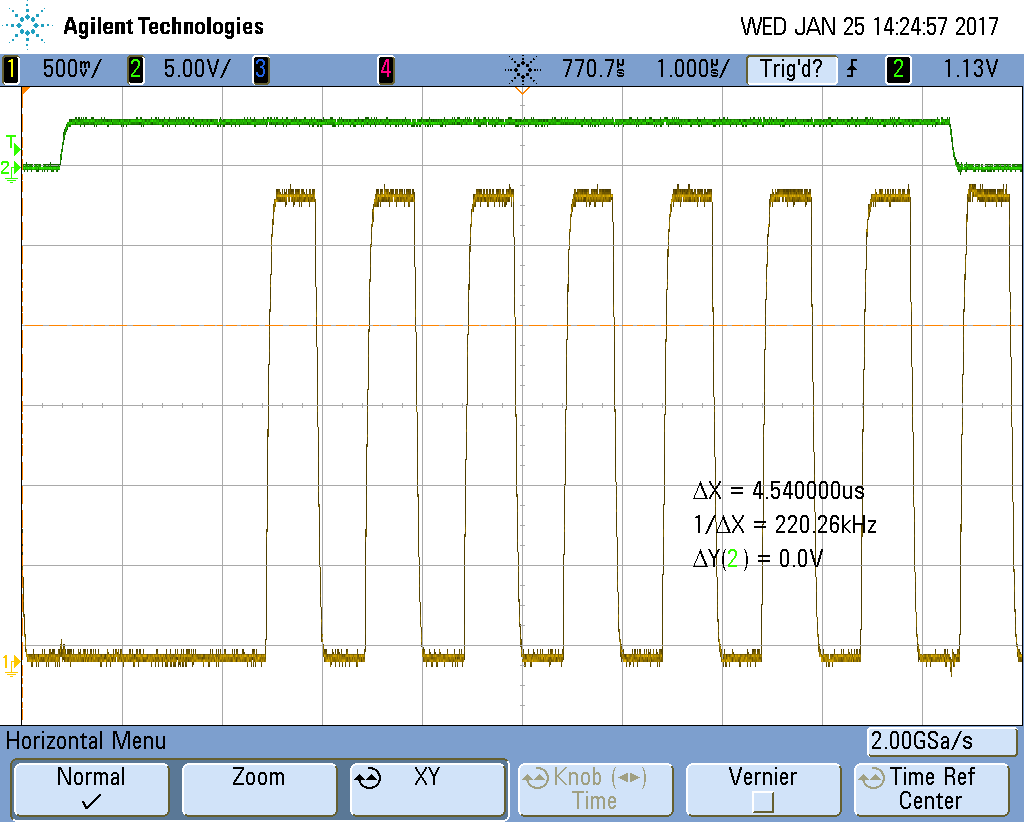
I got my hands on more pro oscilloscope than saleae. I captured problem on MSO7034A. It has 2 GPts/s. It shows there is no spike or noise: image description

But in detail of edge there is some small noise: image description

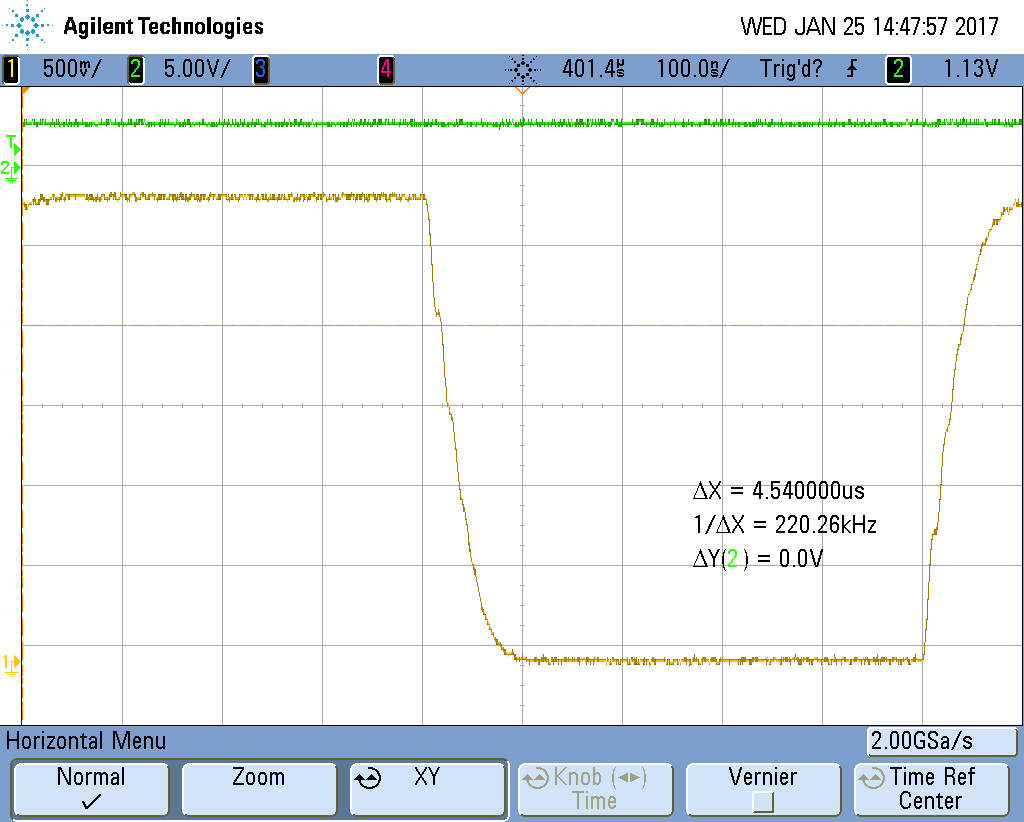
But nothing what a decent Schmidt trigger should not handle. Also I drive the signal from other nordic board, so either transmitter can not have fan out to 2 pin. Or receiver part is broken.

And to save one loop of suggestions - yes I already tried to modify nrf_drv_spi.c and chaged signal strength of SPI_CLK to NRF_GPIO->PIN_CNF[p_config->sck_pin] = ... GPIO_PIN_CNF_DRIVE_H0H1 ...; And no it did not fix the issue.

Could you please reproduce and give solution, other than decreasing SPI speed or using SW?

Parents
  • Yes the screenshot is exactly when it failed. The green line is RDY which shall toggle every 8 falling edges. As you can see on the screenshot it toggled after 7 pulses. I'm not using ribbon cable, but separate cables. Anyway it seems not being problem for SPI module itself only for counter module. Also as I said last time I'm using 1MHz not 8Mhz. I have assumption that when you let counter count then you will end up with more edges than you generate. But true it would be easier reproduce when I could share the source code. Unfortunately I can not. But I did share on private forum. I keep this thread so others can benefit from findings. I could test a filter if there is no better proposal. But I have fear that filter would decrease slope of the edges and could result in making issue even worse.

Reply
  • Yes the screenshot is exactly when it failed. The green line is RDY which shall toggle every 8 falling edges. As you can see on the screenshot it toggled after 7 pulses. I'm not using ribbon cable, but separate cables. Anyway it seems not being problem for SPI module itself only for counter module. Also as I said last time I'm using 1MHz not 8Mhz. I have assumption that when you let counter count then you will end up with more edges than you generate. But true it would be easier reproduce when I could share the source code. Unfortunately I can not. But I did share on private forum. I keep this thread so others can benefit from findings. I could test a filter if there is no better proposal. But I have fear that filter would decrease slope of the edges and could result in making issue even worse.

Children
No Data
Related