This post is older than 2 years and might not be relevant anymore
More Info: Consider searching for newer posts

How to read register from ADXL362 via SPI

Hi,

I have written a short driver for the ADXL362 accelerometer, which I'm attaching here, and I've connected breakout board of the accelerometer from Sparkfun to the nRF51 DK as specified in the picture from the datasheet. I also connected the accelerometer's GND and V+ to the DK's GND and VDD respectively.
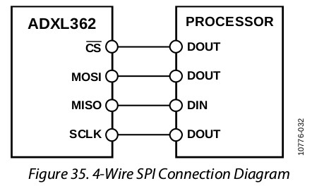
here

In my application, I'm using the driver to read a register in the accelerometer (DEVID_AD in address 0x00) that I understand should always come back with the constant value of 0xAD. However, when debugging the application in Eclipse, the receive buffer is always 0x00.

I'm setting the SPI driver to use mode 0 since the accelerometer's datasheet says it is CPOL = CPHA = 0.

Could any body point out anything I might be doing wrong? The datasheet also says that the accelerometer powers up in standby mode but I figure that SPI comms should always be on.

Thanks in advance

adxl362_spi_drv.c adxl362_spi_drv.h main.c

Parents Reply Children
  • Bjorn,

    I modified the code quite a lot to have the main application configure the driver, and just have the driver run according to that settings. However, using Roger's suggestion is quite easy. To read a register from the accelerometer, you will need a transmit buffer 3 bytes long. One to store the read command (defined ADXL362_READ_REG_CMD), which is 0x0B, the second byte needs to contain the register's address, which in my case is 0x00, and the last byte can be whatever you want. You will need this last byte so while you are transmitting this last one, you will be reading the content of the register you requested. As pointed out by Roger, while you transmit the first two bytes of the tx buffer, you will also be reading bytes that you can ignore and the content of the register read will be on rx_buffer[2] or the third byte of the rx buffer.

    This is the code:

    /**@brief Function for reading ADXL362 registers over SPI.
     *
     * @param[in] address 		ADXL362 Register address
     * @param[in] p_rx_buffer 	Pointer to RX buffer
     * @param[in] bytes 		Number of bytes to be read
     *
     */
    void adxl362_spi_drv_readRegister(uint8_t address, uint8_t * p_rx_buffer, uint8_t bytes)
    {
    	uint32_t err_code;
    
    	//Prepare tx_buffer
    	uint8_t tx_buffer[3];
    	tx_buffer[0] = ADXL362_READ_REG_CMD;
    	tx_buffer[1] = address;
    	tx_buffer[2] = 0x00;
    
    	// Pull chip select line low
    	nrf_gpio_pin_clear(m_spi_config->ss_pin);
    
    	err_code = nrf_drv_spi_transfer(m_spi_master, tx_buffer, sizeof(tx_buffer), p_rx_buffer, sizeof(p_rx_buffer));
    
    	// Set chip select line high
    	nrf_gpio_pin_set(m_spi_config->ss_pin);
    
    	APP_ERROR_CHECK(err_code);
    
    }

    As you can see, the trick is to add an additional byte to the transmit buffer. I you want to receive more than one byte back, you would need to add those additional bytes so as you are sending them, you receive the same number of bytes.

    The new function is pretty much the same, except for a few pointers I used to store SPI configuration and to raise or lower the chip select line required by the SPI protocol.

    Hope this helps.

    -Francisco

Related