This post is older than 2 years and might not be relevant anymore
More Info: Consider searching for newer posts

NRF52 SPI CS Not working after wakeup

We have used a logic analyser to verify this.

SPI initialised and talks nicely with an ADXL362 accelerometer part.

We have interrupts configured.

We go into sd_power_system_off()

Move board, interrupt fires, system wakes up (as no RAM retention or anything)

We re-init the SPI.

We attempt to chat over SPI to the ADXL362.

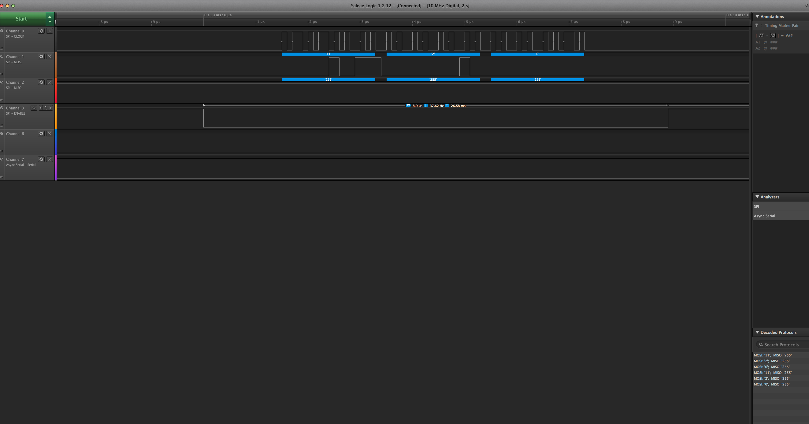
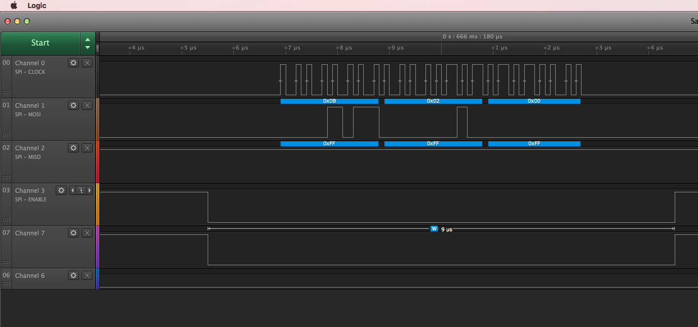
The Clock and the MOSI lines look exactly the same as before the reset (just reading an identity register)

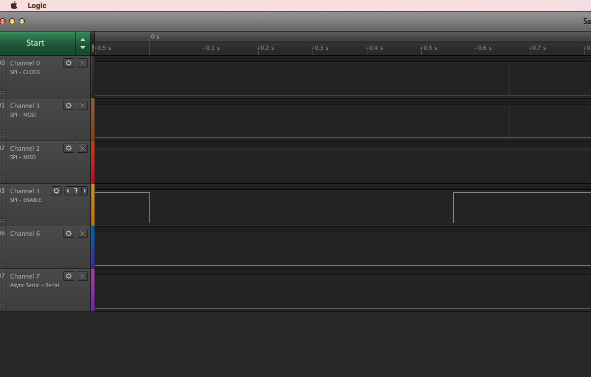
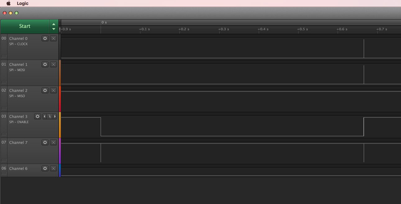
The /CS line is stuck high.

Comparing the logic analyser from the first time where it is driven low during the duration of the transfer shows something is wrong.

Is there a known errata or problem in the SDK?

We have tried on the latest dev kit hardware and it exhibits this.

We are using SDK 11 from memory...

Parents
  • I add some details in support to Chris. We had to run some tests on PCA10040 because it is easier to debug. When we try to read (command 11) the PARTID (register 2) or any other register from the ADXL263 on our device, we always get value 0x0.

    I am providing here few screenshots of some tests run on PCA10040 (without SX9300). Channel 0 to 3 are the SPI lines (Clock, SDI, SDO, Enable).

    image description

    In this first case everything works fine. Then we go into System OFF. Once we come back to System ON (triggering a GPIO pin) we perform the same SPI initialisation and try to read the same register. And this is what happens:

    image description

    SPI is Enabled way before the actual read. Once the read is performed SPI Enable is deasserted. Those 2 spikes (Clock and SDI) correspond to the zoomed signals in the first picture.

    For additional testing we have then modified file "nrf_drv_spi.c". Every time GPIO pin "p_cb->ss_pin" is set/clear we do set/clear the output GPIO pin 20. And this is what we get (before and after System OFF):

    image description

    Before moving into System OFF pin 20 tracks properly SPI Enable signal.

    image description

    And this is what happens after System OFF.

    UPDATE

    We have been running few tests. We made a stripped down version of our code simply performing a SPI read and going into System OFF waiting for an interrupt on a GPIO line. And it works. Then we tried our original code by just changing the GPIO pin assigned to SPI Enable signal (from GPIO 12 to GPIO 17) and it works as well (tested on PCA10040, no sensor actually connected to selected SPI GPIO lines): SPI Enable is going low allowing SPI transactions after coming out of System OFF (see following 2 screenshots).

    image description

    Channel 7 (GPIO 20) is still tracking SPI Enable (GPIO 17). And we still get the initial weird behaviour (GPIO 20 does not follow SPI Enable rising edge). But then we can actually complete the following SPI Read operation.

    image description

    And this is the zoomed view of the SPI transaction.

    In our code GPIO 12 is only used for SPI Enable signal. And in case of mistaken multiple usage of it, I would expect an error to be reported back. But all APP_ERROR_CHECK() are successful. We will now proceed analysing our code in order to track down where and what the error is. Do you have any information about known bugs that might cause such wrong behaviour? It looks like something else is driving GPIO 12. While GPIO 17 is fine.

  • We found the bug. We were using GPIO pin 12 for both a SPI and a TWI interface. The same initialisation procedure was performed both before and after System OFF. The only difference was in the order in which the interfaces were initialised: before System OFF the SPI was initialised first, after System OFF the TWI was first. By swapping the initialisation order, we set what interface is actually controlling (having priority over) the GPIO pins.

Reply
  • We found the bug. We were using GPIO pin 12 for both a SPI and a TWI interface. The same initialisation procedure was performed both before and after System OFF. The only difference was in the order in which the interfaces were initialised: before System OFF the SPI was initialised first, after System OFF the TWI was first. By swapping the initialisation order, we set what interface is actually controlling (having priority over) the GPIO pins.

Children
No Data
Related