This post is older than 2 years and might not be relevant anymore
More Info: Consider searching for newer posts

range distance of nrf52832

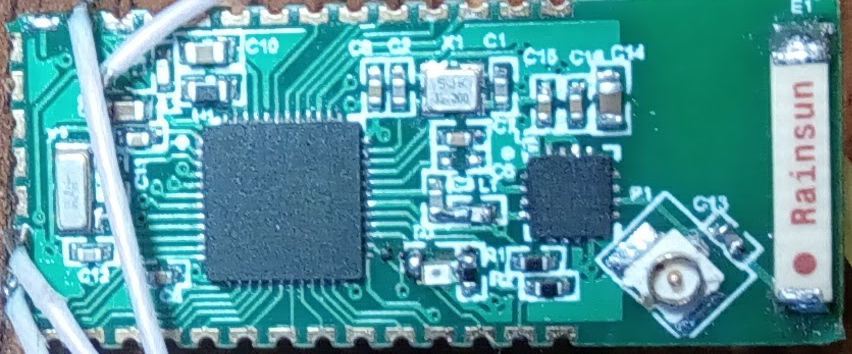
Hello! I've soldered my first board with nrf52832 chip + PA on it. Everything works well beside the radio. The real distance (less 10m) even worse than on nrf52dk despite I use PA RFX2401

Here's my post with schematic pcb of this board, below the photo of that.

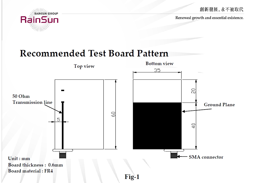
This amplifier is very popular for nrf chips especially nrf2401 and the range distance is about 500m-1km. Also the amplifier used for nrf51822.

The circuit for nrf52832 is standart from nordic documentation, the circuit in part of PA from datasheet

For enabling work of PA I set high level on pins 23,24 (due to absence special pins for that like in nrf51822)

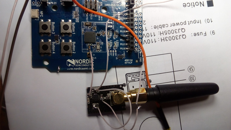
Also I tried to connect external antenna via IPEX socket, the result was a little bit better.

The power amplifier should increase strength of signal up to +20dbm, in my case where nrf52dk has -55dbm - my board has -30dbm but when I far away (with smartphone nrf_connect app) from boards phone keeps get advertising packets from nrf52dk and start to loose some from my board.

I know this board is not very well done in part of radio (not enough vias for good ground plane).

I've even tried to use amplifier part of nrf2401+PA module with external antenna connect to my board. I've tried the same even with nrf52dk :)) (attahched photo below). Actually the result is the same. (Maybe it's not correct way to test PA but I had to test it)

I need the distance about 100-200m with one - two concrete wall or through 7-10mm metal

image description

image description

Parents
  • You can't hang the micro coax (ie, hirose) connector off the antenna like that. That would make an open stub tuner which at these frequencies probably makes a dead short. If you want a coax port you will need to have it selectable with parts placement. Just replicate C13 and have them share a common pad then you place the cap for the solution you want.

    Also L1 cannot be 15nH. Off hand I don't know what reference design calls for but 15nH makes an open circuit at 2.4GHz.

    These mistakes alone will cause you design to not work. Though you should also check the code on your logic for TxEN and RxEn. The bluetooth transmissions are really short so you should use a O-scope and RF power detector to make sure everything lines up correctly. On the code I was involved in an extensive post on PA/LNA support on nRF52832. Here: devzone.nordicsemi.com/.../

    With regard to the antenna: the ground plane, feed and placement of the antenna are incorrect. RainSun specify a vertical orientation for the antenna with 50ohm feed to the antenna and the feedpoint right where the ground plane ends. See below: RainSunAntenna

  • Let me try to clarify this: You CAN NOT have the micro-coax connector placed on the microstrip as I see it in the photo and on the schematic. That connector, though unconnected to anything, will appear as a short to the RF. Similarly if you remove the chip antenna and try to test using just the micro coax the small trace up to the cap will de-tune the feed to the micro-coax. Finally, your microstrips are definitely not characterized to 50ohms. It is very obvious from their size that even if there is a ground plane below them they are simply not wide enough to be 50ohms. This will significantly detune the output in addition to the other errors that I noted above. Further the RFX2401 is not unconditionally stable. It says that right in the spec sheet. So your mistakes on the RF likely have resulted in it oscillating instead of operating strictly as an amplifier.

Reply
  • Let me try to clarify this: You CAN NOT have the micro-coax connector placed on the microstrip as I see it in the photo and on the schematic. That connector, though unconnected to anything, will appear as a short to the RF. Similarly if you remove the chip antenna and try to test using just the micro coax the small trace up to the cap will de-tune the feed to the micro-coax. Finally, your microstrips are definitely not characterized to 50ohms. It is very obvious from their size that even if there is a ground plane below them they are simply not wide enough to be 50ohms. This will significantly detune the output in addition to the other errors that I noted above. Further the RFX2401 is not unconditionally stable. It says that right in the spec sheet. So your mistakes on the RF likely have resulted in it oscillating instead of operating strictly as an amplifier.

Children
No Data
Related