This post is older than 2 years and might not be relevant anymore
More Info: Consider searching for newer posts

wt is the difference bw PWM driver and PWM Library example

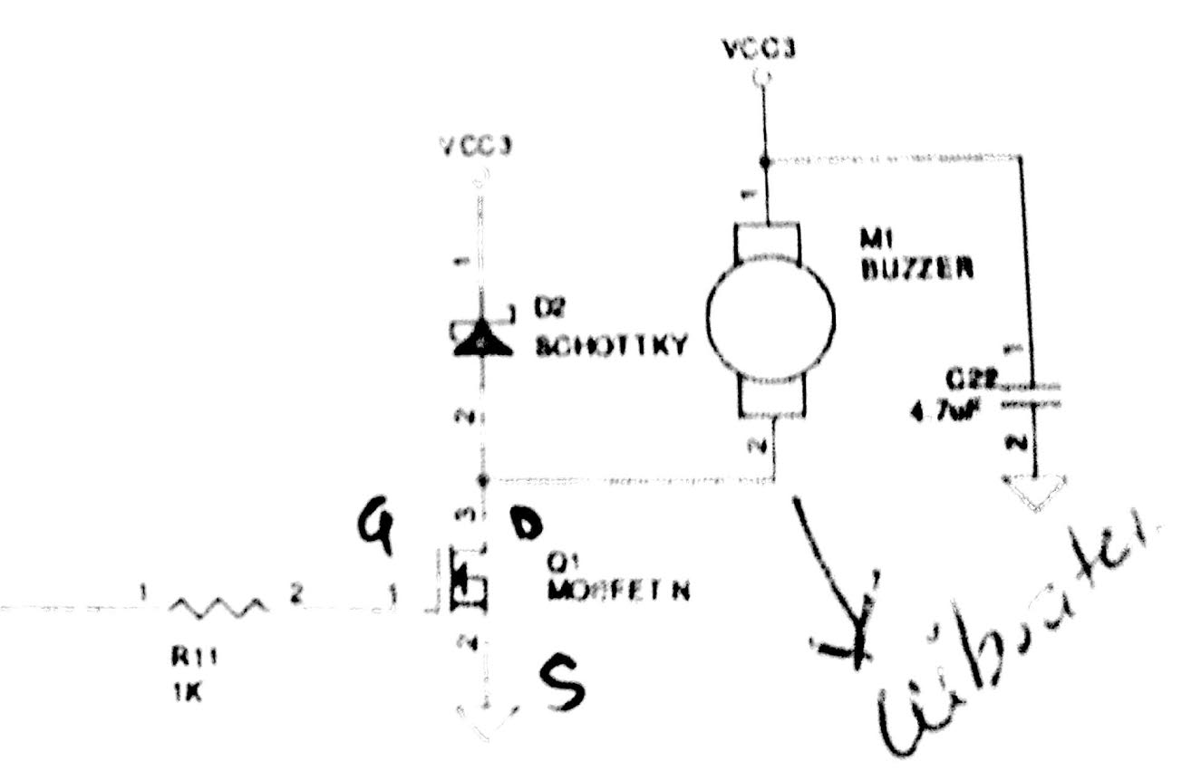
unnamed.jpg(/attachment/182b723590b3c447267d5aed62b5405f)hi, i want to work on PWM to controll the vibration coin frequency for certain time period and also to change RGB values of LEDs so which example i can choose to understand PWM on nRF52.

#Edit:- /* Switch the polarity of the second channel. */ //pwm1_cfg.pin_polarity[1] = APP_PWM_POLARITY_ACTIVE_HIGH;

   /* Initialize and enable PWM. */
   err_code = app_pwm_init(&PWM,&pwm1_cfg,pwm_ready_callback);
   APP_ERROR_CHECK(err_code);
   app_pwm_enable(&PWM);

   uint32_t value;

      APP_ERROR_CHECK(err_code);
   while(true)
   {

       for (uint8_t i = 0; i < 40; ++i)
       {
           value = (i < 20) ? (i * 5) : (100 - (i - 20) * 5);
           //printf("value = %d\n",value);
           ready_flag = false;
           /* Set the duty cycle - keep trying until PWM is ready... */
           while (app_pwm_channel_duty_set(&PWM, 0, value) == NRF_ERROR_BUSY);

           /* ... or wait for callback. */
           while(!ready_flag);
           APP_ERROR_CHECK(app_pwm_channel_duty_set(&PWM, 1, value));
           nrf_delay_ms(50);

       }

   }
Parents
  • Hello saiteja

    The PWM driver and library provide two ways of generating a PWM signal on the nRF52. The PWM driver uses dedicated hardware to generate the signal, while the PWM library uses GPIOTE, PPI and timers in combination.

    For more information on the two and their properties please see the following links to the infocenter

    PWM driver (dedicated hardware):

    infocenter.nordicsemi.com/index.jsp

    PWM library (GPIOTE, PPI and timers):

    infocenter.nordicsemi.com/.../lib_pwm.html

    You can find links to descriptions of the examples you mentioned (pwm_driver and pwm_library in the examples->peripheral folder) on the pages of the infocenter links above.

    Best regards

    Jørn Frøysa

  • You can use either the PWM driver with its dedicated hardware or you can use the PWM library.

    In the PWM library example you can change the frequency of the PWM signal by uninitializing the PWM instance, changing the .period_us value in pwm1_cfg, and then initializing the PWM instance again.

    The while loops in the example are used to change how quickly the leds ramp up and down by changing the duty cycle of the PWM signal. These are not needed if you only intend to change the frequency.

    To only send for a few seconds you can use a timer, and in the callback function you can stop the PWM and change its frequency if needed.

    What voltage do you have on the output of your LPF? According to the datasheet of the C0820B006F it has an operating voltage requirement of 2.7 – 3.3 V DC.

    Best regards

    Jørn Frøysa

Reply
  • You can use either the PWM driver with its dedicated hardware or you can use the PWM library.

    In the PWM library example you can change the frequency of the PWM signal by uninitializing the PWM instance, changing the .period_us value in pwm1_cfg, and then initializing the PWM instance again.

    The while loops in the example are used to change how quickly the leds ramp up and down by changing the duty cycle of the PWM signal. These are not needed if you only intend to change the frequency.

    To only send for a few seconds you can use a timer, and in the callback function you can stop the PWM and change its frequency if needed.

    What voltage do you have on the output of your LPF? According to the datasheet of the C0820B006F it has an operating voltage requirement of 2.7 – 3.3 V DC.

    Best regards

    Jørn Frøysa

Children
No Data
Related