
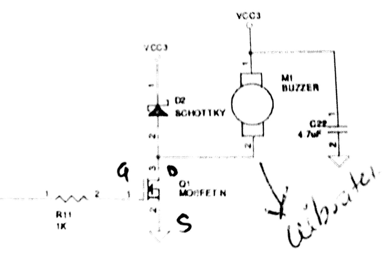
 (/attachment/182b723590b3c447267d5aed62b5405f)hi, i want to work on PWM to controll the vibration coin frequency for certain time period and also to change RGB values of LEDs so which example i can choose to understand PWM on nRF52.
#Edit:- /* Switch the polarity of the second channel. */ //pwm1_cfg.pin_polarity[1] = APP_PWM_POLARITY_ACTIVE_HIGH;
   /* Initialize and enable PWM. */
   err_code = app_pwm_init(&PWM,&pwm1_cfg,pwm_ready_callback);
   APP_ERROR_CHECK(err_code);
   app_pwm_enable(&PWM);

   uint32_t value;

      APP_ERROR_CHECK(err_code);
   while(true)
   {

       for (uint8_t i = 0; i < 40; ++i)
       {
           value = (i < 20) ? (i * 5) : (100 - (i - 20) * 5);
           //printf("value = %d\n",value);
           ready_flag = false;
           /* Set the duty cycle - keep trying until PWM is ready... */
           while (app_pwm_channel_duty_set(&PWM, 0, value) == NRF_ERROR_BUSY);

           /* ... or wait for callback. */
           while(!ready_flag);
           APP_ERROR_CHECK(app_pwm_channel_duty_set(&PWM, 1, value));
           nrf_delay_ms(50);

       }

   }
