This post is older than 2 years and might not be relevant anymore
More Info: Consider searching for newer posts

nRF8001 Antenna Matching Network

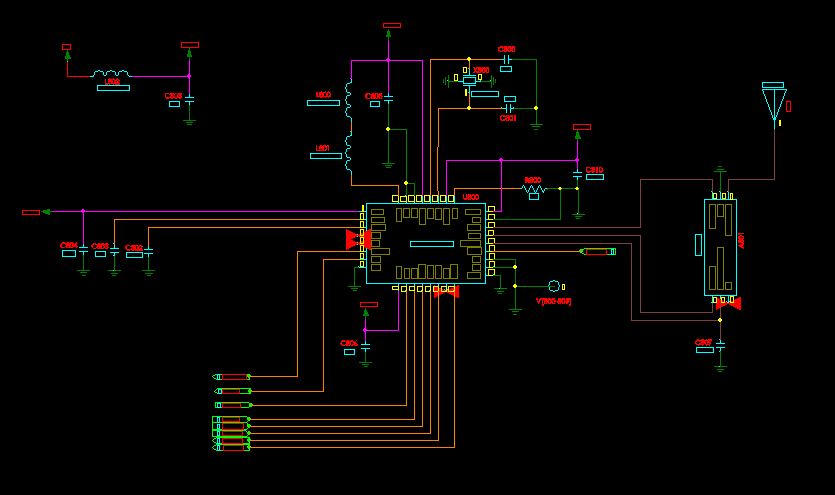
I’m using nRF8001-R2Q32-T in my design, RF Balun (part number: 2450BM14A0002T), and 2.4GHz Chip RF Antenna (part number 2450AT18A100E). My question do I still use any network (capacitor, inductor, resistor) or the Balun is taking care of that. Is that mean that i don't have to worry as long as I'm using the correct Balun

Thank you Dino

image description

Parents
  • Without seeing the actual layout it is impossible to say you did it correctly.

    But in terms of the schematic, yes what you did is correct. The balun replaces the external match/balun circuit for the nRF8001 and the antenna is spec'd to be 9.5dB return loss without a match.

    However, I should stress than any deviation from Johanson's design guidelines will cause you to have a mismatch condition and an antenna that doesn't broadcast. So all the trace lengths, trace widths and ground planes need to be precisely correct.

    Also Johanson does highly encourage one to place a pi network ahead of the antenna to fix any matching problems that might show up on the antenna side of the problem. I would encourage you to do this as well. Also, the pi network can help out with harmonic filtering if you ever decide to go through certification.

    A few weeks back I walked someone through all the layout issues with a similar design using the 51822. Here is the final design which was done correctly: http://imgur.com/a/33xSx

    Here is a link to the original post: devzone.nordicsemi.com/.../

Reply
  • Without seeing the actual layout it is impossible to say you did it correctly.

    But in terms of the schematic, yes what you did is correct. The balun replaces the external match/balun circuit for the nRF8001 and the antenna is spec'd to be 9.5dB return loss without a match.

    However, I should stress than any deviation from Johanson's design guidelines will cause you to have a mismatch condition and an antenna that doesn't broadcast. So all the trace lengths, trace widths and ground planes need to be precisely correct.

    Also Johanson does highly encourage one to place a pi network ahead of the antenna to fix any matching problems that might show up on the antenna side of the problem. I would encourage you to do this as well. Also, the pi network can help out with harmonic filtering if you ever decide to go through certification.

    A few weeks back I walked someone through all the layout issues with a similar design using the 51822. Here is the final design which was done correctly: http://imgur.com/a/33xSx

    Here is a link to the original post: devzone.nordicsemi.com/.../

Children
No Data
Related