Edit: The code posted below works on the 96x96 3V(LS013B4DN04) variant of the display, I still have no idea why it doesn't work on LS044Q7DH01, but I'm guessing it doesnt have much to do with the nordic chip. I'll post an update here if I get a reply from Sharp..
Edit2: Mystery solved..... Clearly these are somewhat fragile..
Hi developers. I've seen this been asked before but the answers don't really show me any working examples.
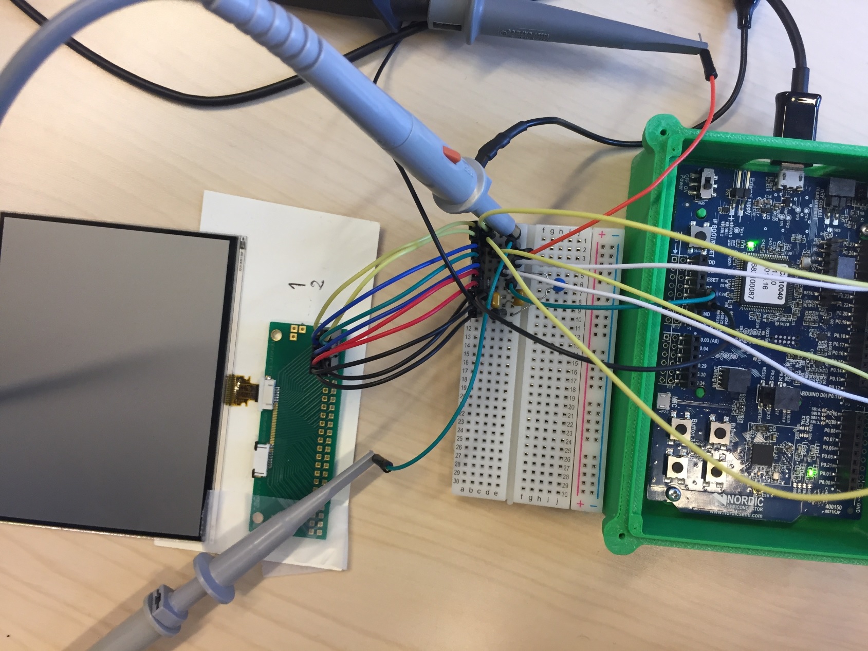
Setup picture

I get no response from the display (not even when I power on..?). I am fairly certain I have connected it correct, I made as simple code as meaningfully possible, and I have a scope on the SCLK, SS and MOSI line
i feel i've checked "everything"
- Connection on FPC contact, and order of pins
- SPI signal
- Timing on init
- Tried all combinations of SPI modes and CS configs
- Timing on SPI signal
- Lower SPI frequencies
- Voltage levels
- (but I am pretty sure there must be something i've missed)
Would appreciate any insight so I can get any further..
Code that works on LS013B4DN04:
#include <stdint.h>
#include "nrf_delay.h"
#include "boards.h"
#include "nrf_drv_spi.h"

#define DISP_SPI_INSTANCE 1

#define DISP_SS_PIN 12
#define SCLK_DISP 22
#define MOSI_DISP 23
#define DISP_VCOM 24                /**< VCOM has to be toggled since EXTMODE = H */

#define DISPLAY_CS_IDLE         nrf_gpio_pin_write(DISP_SS_PIN, 0) // Set CS pin low
#define DISPLAY_CS_ACTIVE       nrf_gpio_pin_write(DISP_SS_PIN, 1) // Set CS pin high

// Commands
#define MLCD_WR 0x80 //MLCD write line command
#define MLCD_CM 0x20 //MLCD clear memory command
#define MLCD_NO 0x00 //MLCD NOP command (used to switch VCOM)

//LCD resolution
#define MLCD_XRES 320 //pixels per horizontal line
#define MLCD_YRES 240 //pixels per vertical line
#define MLCD_BYTES_LINE MLCD_XRES / 8 //number of bytes in a line
#define MLCD_BUF_SIZE MLCD_YRES * MLCD_BYTES_LINE

//defines the VCOM bit in the command word that goes to the LCD
#define VCOM_HI 0x40
#define VCOM_LO 0x00

#define HIGH 1
#define LOW 0

#define DISP_ON_PIN 11

static const unsigned char BitReverseTable256[] =
{
  0x00, 0x80, 0x40, 0xC0, 0x20, 0xA0, 0x60, 0xE0, 0x10, 0x90, 0x50, 0xD0, 0x30, 0xB0, 0x70, 0xF0,
  0x08, 0x88, 0x48, 0xC8, 0x28, 0xA8, 0x68, 0xE8, 0x18, 0x98, 0x58, 0xD8, 0x38, 0xB8, 0x78, 0xF8,
  0x04, 0x84, 0x44, 0xC4, 0x24, 0xA4, 0x64, 0xE4, 0x14, 0x94, 0x54, 0xD4, 0x34, 0xB4, 0x74, 0xF4,
  0x0C, 0x8C, 0x4C, 0xCC, 0x2C, 0xAC, 0x6C, 0xEC, 0x1C, 0x9C, 0x5C, 0xDC, 0x3C, 0xBC, 0x7C, 0xFC,
  0x02, 0x82, 0x42, 0xC2, 0x22, 0xA2, 0x62, 0xE2, 0x12, 0x92, 0x52, 0xD2, 0x32, 0xB2, 0x72, 0xF2,
  0x0A, 0x8A, 0x4A, 0xCA, 0x2A, 0xAA, 0x6A, 0xEA, 0x1A, 0x9A, 0x5A, 0xDA, 0x3A, 0xBA, 0x7A, 0xFA,
  0x06, 0x86, 0x46, 0xC6, 0x26, 0xA6, 0x66, 0xE6, 0x16, 0x96, 0x56, 0xD6, 0x36, 0xB6, 0x76, 0xF6,
  0x0E, 0x8E, 0x4E, 0xCE, 0x2E, 0xAE, 0x6E, 0xEE, 0x1E, 0x9E, 0x5E, 0xDE, 0x3E, 0xBE, 0x7E, 0xFE,
  0x01, 0x81, 0x41, 0xC1, 0x21, 0xA1, 0x61, 0xE1, 0x11, 0x91, 0x51, 0xD1, 0x31, 0xB1, 0x71, 0xF1,
  0x09, 0x89, 0x49, 0xC9, 0x29, 0xA9, 0x69, 0xE9, 0x19, 0x99, 0x59, 0xD9, 0x39, 0xB9, 0x79, 0xF9,
  0x05, 0x85, 0x45, 0xC5, 0x25, 0xA5, 0x65, 0xE5, 0x15, 0x95, 0x55, 0xD5, 0x35, 0xB5, 0x75, 0xF5,
  0x0D, 0x8D, 0x4D, 0xCD, 0x2D, 0xAD, 0x6D, 0xED, 0x1D, 0x9D, 0x5D, 0xDD, 0x3D, 0xBD, 0x7D, 0xFD,
  0x03, 0x83, 0x43, 0xC3, 0x23, 0xA3, 0x63, 0xE3, 0x13, 0x93, 0x53, 0xD3, 0x33, 0xB3, 0x73, 0xF3,
  0x0B, 0x8B, 0x4B, 0xCB, 0x2B, 0xAB, 0x6B, 0xEB, 0x1B, 0x9B, 0x5B, 0xDB, 0x3B, 0xBB, 0x7B, 0xFB,
  0x07, 0x87, 0x47, 0xC7, 0x27, 0xA7, 0x67, 0xE7, 0x17, 0x97, 0x57, 0xD7, 0x37, 0xB7, 0x77, 0xF7,
  0x0F, 0x8F, 0x4F, 0xCF, 0x2F, 0xAF, 0x6F, 0xEF, 0x1F, 0x9F, 0x5F, 0xDF, 0x3F, 0xBF, 0x7F, 0xFF
};

static char vComState = 0;

static const nrf_drv_spi_t disp_spi = NRF_DRV_SPI_INSTANCE(DISP_SPI_INSTANCE);  /**< SPI instance. */

void LS044Q7DH01_Init(void){
    uint32_t err_code;
    // SPI Init
    nrf_drv_spi_config_t disp_spi_config = NRF_DRV_SPI_DEFAULT_CONFIG;
    disp_spi_config.ss_pin   = NULL;
    disp_spi_config.miso_pin = NULL;
    disp_spi_config.mosi_pin = MOSI_DISP;
    disp_spi_config.sck_pin  = SCLK_DISP;
    disp_spi_config.mode = NRF_DRV_SPI_MODE_0;
    disp_spi_config.orc = 0x00;
    disp_spi_config.frequency = NRF_DRV_SPI_FREQ_1M;
    disp_spi_config.bit_order = NRF_DRV_SPI_BIT_ORDER_MSB_FIRST;

    err_code = nrf_drv_spi_init(&disp_spi, &disp_spi_config, NULL);
    APP_ERROR_CHECK(err_code);

    nrf_gpio_cfg_output(DISP_SS_PIN);
    DISPLAY_CS_IDLE;
    nrf_gpio_cfg_output(DISP_VCOM);
    // SPI init done
}

void dispTest(unsigned char in, uint8_t line){
    uint32_t err_code;

    line = BitReverseTable256[line];
    unsigned char dataToSend[16] = {MLCD_WR, line, // Start with write, line addr, data
        in, in, in, in, in, in, in, in, in, in,
        in, in,
        0x00}; // end with zero trailer

    DISPLAY_CS_ACTIVE;
    err_code = nrf_drv_spi_transfer(&disp_spi, dataToSend, 16, NULL, NULL);
    APP_ERROR_CHECK(err_code);
    DISPLAY_CS_IDLE;
}

void dispToggleVCOM(void){
    // Toggle pin (if EXTMODE = H)
    nrf_gpio_pin_toggle(DISP_VCOM);

    // Send toggle message (if EXTMODE = L)
    /*
    unsigned char dataToSend[2] = {0x00, 0x00};
    if (vComState) dataToSend[0] = VCOM_HI;
    else dataToSend[0] = VCOM_LO;
    vComState = 1 - vComState;
    DISPLAY_CS_ACTIVE;
    nrf_drv_spi_transfer(&disp_spi, dataToSend, 2, NULL, NULL);
    DISPLAY_CS_IDLE;
    */
}

void dispClear(void){
    unsigned char dataToSend[2] = {MLCD_CM, 0x00};
    DISPLAY_CS_ACTIVE;
    nrf_drv_spi_transfer(&disp_spi, dataToSend, 2, NULL, NULL);
    DISPLAY_CS_IDLE;
}


int main(void){
    /* Configure board. */
    bsp_board_leds_init();
    nrf_delay_us(100);
    nrf_gpio_cfg_output(DISP_ON_PIN);
    nrf_gpio_pin_write(DISP_ON_PIN, HIGH);
    nrf_delay_us(100);
    LS044Q7DH01_Init();
    dispClear();
    nrf_delay_us(200);
    while(1){
        unsigned char i = 0;
        unsigned char y = 96;
        for(i = 0; i<= y; i++){
            dispTest(0x00, i);
            dispToggleVCOM();
            nrf_delay_ms(10);
        }
        for(i = 0; i<= y; i++){
            dispTest(0xFF, i);
            dispToggleVCOM();
            nrf_delay_ms(10);
        }
        //nrf_delay_ms(1000);
        dispClear();
        //nrf_delay_ms(1000);
        dispToggleVCOM();
        bsp_board_led_invert(1);
    }
}

