This post is older than 2 years and might not be relevant anymore
More Info: Consider searching for newer posts

52832 master, through the I2S interface to transmit voice data to the DAC player

Hi,

Currently I have a problem with the use of 52832 I2S interface to transmit voice, the transmission is not coherent.

Here is my initialization code

	// Enable reception
NRF_I2S->CONFIG.RXEN = (I2S_CONFIG_RXEN_RXEN_Enabled << I2S_CONFIG_RXEN_RXEN_Pos);
// Enable transmission
NRF_I2S->CONFIG.TXEN = (I2S_CONFIG_TXEN_TXEN_Enabled << I2S_CONFIG_TXEN_TXEN_Pos);
// Enable MCK generator
NRF_I2S->CONFIG.MCKEN = (I2S_CONFIG_MCKEN_MCKEN_Enabled << I2S_CONFIG_MCKEN_MCKEN_Pos);
// MCKFREQ = 16 kHz
NRF_I2S->CONFIG.MCKFREQ = I2S_CONFIG_MCKFREQ_MCKFREQ_32MDIV21 << I2S_CONFIG_MCKFREQ_MCKFREQ_Pos;
// Ratio = 96
NRF_I2S->CONFIG.RATIO = I2S_CONFIG_RATIO_RATIO_96X << I2S_CONFIG_RATIO_RATIO_Pos;
// MCKFREQ = 4 MHz and Ratio = 256 gives sample rate = 15.625 ks/s
// Sample width = 16 bit
NRF_I2S->CONFIG.SWIDTH = I2S_CONFIG_SWIDTH_SWIDTH_16Bit << I2S_CONFIG_SWIDTH_SWIDTH_Pos;
// Alignment = Left
NRF_I2S->CONFIG.ALIGN = I2S_CONFIG_ALIGN_ALIGN_Left << I2S_CONFIG_ALIGN_ALIGN_Pos;
// Format = I2S
NRF_I2S->CONFIG.FORMAT = I2S_CONFIG_FORMAT_FORMAT_I2S << I2S_CONFIG_FORMAT_FORMAT_Pos;
// Use Left
NRF_I2S->CONFIG.CHANNELS = I2S_CONFIG_CHANNELS_CHANNELS_Left << I2S_CONFIG_CHANNELS_CHANNELS_Pos;

// MCK routed to pin 20
NRF_I2S->PSEL.MCK = (20 << I2S_PSEL_MCK_PIN_Pos) | (I2S_PSEL_MCK_CONNECT_Connected << I2S_PSEL_MCK_CONNECT_Pos);
// SCK routed to pin 22
NRF_I2S->PSEL.SCK = (22 << I2S_PSEL_SCK_PIN_Pos) | (I2S_PSEL_SCK_CONNECT_Connected << I2S_PSEL_SCK_CONNECT_Pos);
// LRCK routed to pin 23
NRF_I2S->PSEL.LRCK = (23 << I2S_PSEL_LRCK_PIN_Pos) | (I2S_PSEL_LRCK_CONNECT_Connected <<I2S_PSEL_LRCK_CONNECT_Pos);
// SDOUT routed to pin 24
NRF_I2S->PSEL.SDOUT = (24 << I2S_PSEL_SDOUT_PIN_Pos) | (I2S_PSEL_SDOUT_CONNECT_Connected << I2S_PSEL_SDOUT_CONNECT_Pos);
// SDIN routed on pin 25
NRF_I2S->PSEL.SDIN = (25 << I2S_PSEL_SDIN_PIN_Pos) | (I2S_PSEL_SDIN_CONNECT_Connected << I2S_PSEL_SDIN_CONNECT_Pos);

NRF_I2S->TXD.PTR = *my_tx_buf;
NRF_I2S->RXD.PTR = *my_rx_buf;
NRF_I2S->RXTXD.MAXCNT = MY_BUF_SIZE;

NRF_I2S->ENABLE = 1;

NRF_I2S->TASKS_START = 1;

Use of the data book routines.

Here is my data transfer code.

		NRF_I2S->TXD.PTR = *BufferTx;
	NRF_I2S->EVENTS_TXPTRUPD = 0;

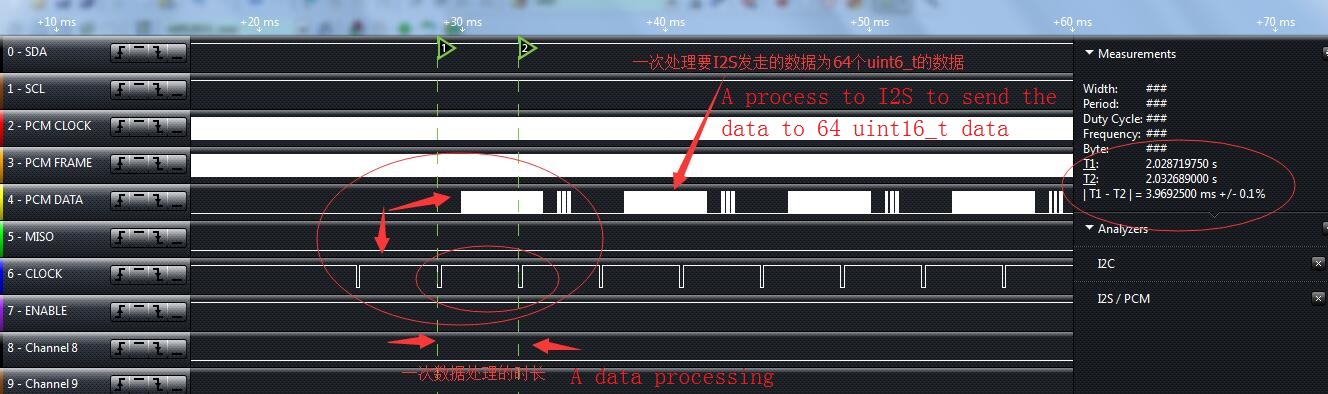
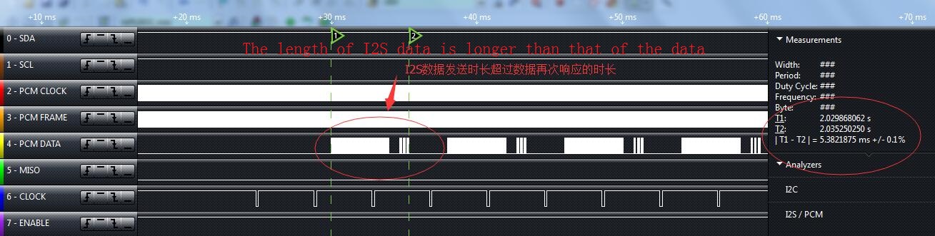
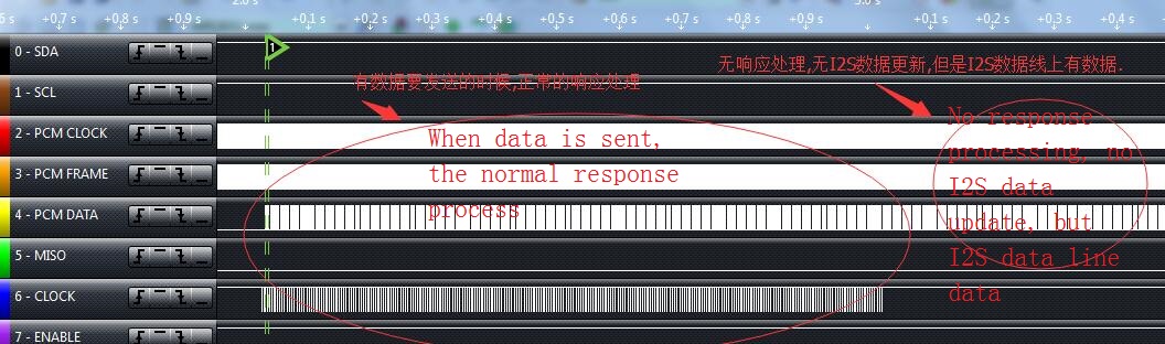
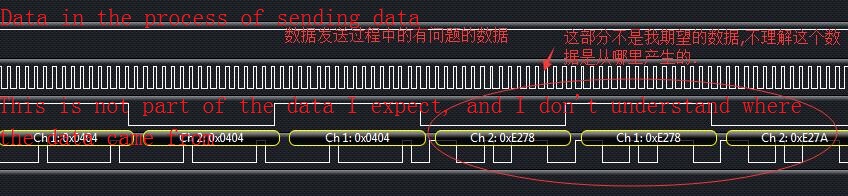
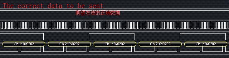
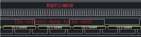
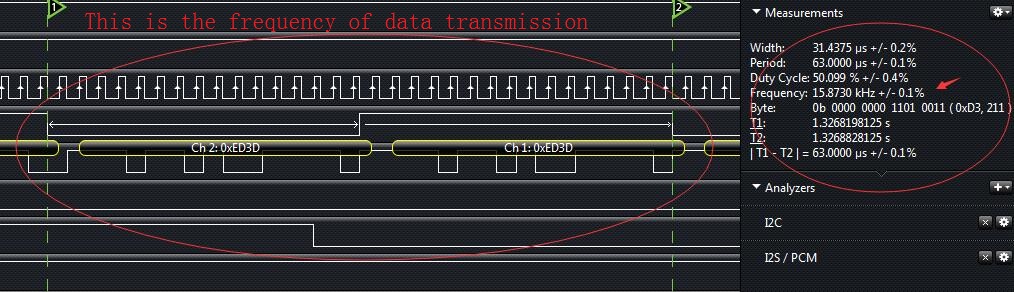
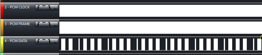
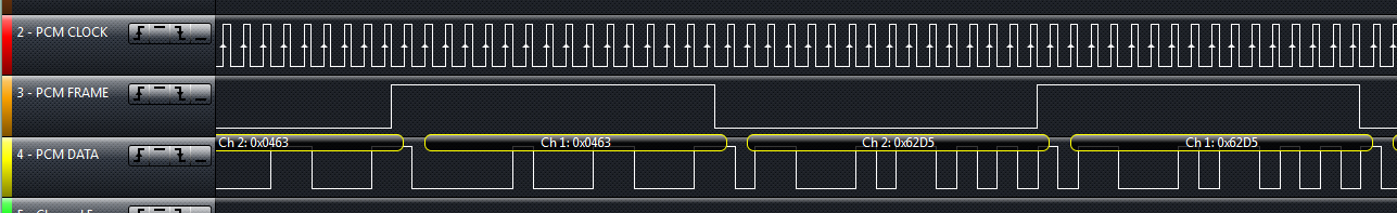
The data captured by the logic analyzer is used to indicate that the data is not coherent. image description

image description

I would like to ask whether the I2S interface configuration is correct or a reference routines, thank you!

Parents
  • Hi Jørn,

    But the problem has not been resolved, I hope you can continue to help.

    Here is the code I modified according to your opinion:

    #define MY_BUF_SIZE		64
    

    static uint32_t my_tx_buf[MY_BUF_SIZE];

    static uint32_t my_rx_buf[MY_BUF_SIZE];

    Initialization:

    	// Enable reception
    NRF_I2S->CONFIG.RXEN = (I2S_CONFIG_RXEN_RXEN_Enabled << I2S_CONFIG_RXEN_RXEN_Pos);
    // Enable transmission
    NRF_I2S->CONFIG.TXEN = (I2S_CONFIG_TXEN_TXEN_Enabled << I2S_CONFIG_TXEN_TXEN_Pos);
    // Enable MCK generator
    NRF_I2S->CONFIG.MCKEN = (I2S_CONFIG_MCKEN_MCKEN_Enabled << I2S_CONFIG_MCKEN_MCKEN_Pos);
    // MCKFREQ = 16 kHz
    NRF_I2S->CONFIG.MCKFREQ = I2S_CONFIG_MCKFREQ_MCKFREQ_32MDIV21 << I2S_CONFIG_MCKFREQ_MCKFREQ_Pos;
    // Ratio = 96
    NRF_I2S->CONFIG.RATIO = I2S_CONFIG_RATIO_RATIO_96X << I2S_CONFIG_RATIO_RATIO_Pos;
    // MCKFREQ = 4 MHz and Ratio = 256 gives sample rate = 15.625 ks/s
    // Sample width = 16 bit
    NRF_I2S->CONFIG.SWIDTH = I2S_CONFIG_SWIDTH_SWIDTH_16Bit << I2S_CONFIG_SWIDTH_SWIDTH_Pos;
    // Alignment = Left
    NRF_I2S->CONFIG.ALIGN = I2S_CONFIG_ALIGN_ALIGN_Left << I2S_CONFIG_ALIGN_ALIGN_Pos;
    // Format = I2S
    NRF_I2S->CONFIG.FORMAT = I2S_CONFIG_FORMAT_FORMAT_I2S << I2S_CONFIG_FORMAT_FORMAT_Pos;
    // Use Left
    NRF_I2S->CONFIG.CHANNELS = I2S_CONFIG_CHANNELS_CHANNELS_Left << I2S_CONFIG_CHANNELS_CHANNELS_Pos;
    
    // MCK routed to pin 20
    NRF_I2S->PSEL.MCK = (20 << I2S_PSEL_MCK_PIN_Pos) | (I2S_PSEL_MCK_CONNECT_Connected << I2S_PSEL_MCK_CONNECT_Pos);
    // SCK routed to pin 22
    NRF_I2S->PSEL.SCK = (22 << I2S_PSEL_SCK_PIN_Pos) | (I2S_PSEL_SCK_CONNECT_Connected << I2S_PSEL_SCK_CONNECT_Pos);
    // LRCK routed to pin 23
    NRF_I2S->PSEL.LRCK = (23 << I2S_PSEL_LRCK_PIN_Pos) | (I2S_PSEL_LRCK_CONNECT_Connected <<I2S_PSEL_LRCK_CONNECT_Pos);
    // SDOUT routed to pin 24
    NRF_I2S->PSEL.SDOUT = (24 << I2S_PSEL_SDOUT_PIN_Pos) | (I2S_PSEL_SDOUT_CONNECT_Connected << I2S_PSEL_SDOUT_CONNECT_Pos);
    // SDIN routed on pin 25
    NRF_I2S->PSEL.SDIN = (25 << I2S_PSEL_SDIN_PIN_Pos) | (I2S_PSEL_SDIN_CONNECT_Connected << I2S_PSEL_SDIN_CONNECT_Pos);
    
    NRF_I2S->TXD.PTR = (uint32_t)my_tx_buf;
    NRF_I2S->RXD.PTR = (uint32_t)my_rx_buf;
    NRF_I2S->RXTXD.MAXCNT = MY_BUF_SIZE;
    
    NRF_I2S->ENABLE = 1;
    
    NRF_I2S->TASKS_START = 1;
    

    Data transmission:

    void QcyI2sDataSend(uint32_t *BufferTx,uint16_t BufferTxLen)

    {

    if(NRF_I2S->EVENTS_TXPTRUPD != 0)
    
    {
    

    // NRF_I2S->ENABLE = 1;

    // NRF_I2S->TASKS_START = 1;

    	NRF_I2S->TXD.PTR = (uint32_t)BufferTx;
    
    	NRF_I2S->EVENTS_TXPTRUPD = 0;
    
    }
    

    }

    Here are the results of the test.

    image description image description image description image description image description image description image description

    I don't know what's going to happen, but it affects woxit.

    Look forward to your answer, thank you!

  • Hi Jørn,

    Thank you for your reply, the translation of the text on the picture will be uploaded in the subsequent comments, please help continue to answer, thank you!

Reply Children
No Data
Related