This post is older than 2 years and might not be relevant anymore
More Info: Consider searching for newer posts

FCC Certification /Digital modulation minimum bandwitdth

Hi all,

Our company is in the process of certifying a device. This device is using a nrf52832 with radio.

We had no problem to comply with the ETSI standard, but things didn't go as expected for FCC certification.

The FCC §15.247 says that for systems using digital modulation, the minimum 6 dB bandwidth shall be at least 500 kHz.

This is the radio setting I used: Tx Power = -4dBm, Frequency = 2402Mhz, Mode = 1Mbit

This is the result obtain by the test lab:
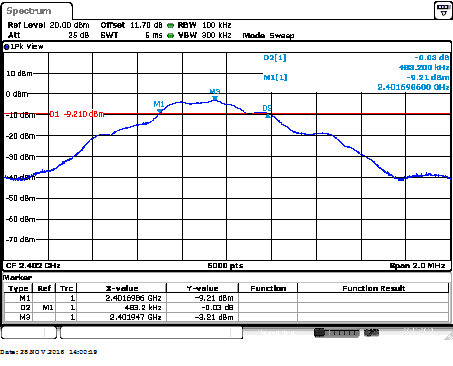
image description

They found the highest point M3 and draw a line at -6dB. The bandwidth at -6dB from M3 should be at least 500kHz. Unfortunately from the test lab results, the bandwidth is only 483.2 kHz.

So my question is, is there a firmware way to changing the bandwidth for a fixe channel?

Thanks in advance for the help, Stéphane Lovejoy

Parents
  • Without extensive testing of your design, it is impossible to tell exactly what is going wrong on your test. However, there are a few things that stand out:

    1. There is a little too much attenuation ahead of a spectrum analyzer. As a result the noise floor seems to be unusually high at about -40dBm. Or, maybe not. Hard to tell unless one spans out. The excess noise floor tends to compress the overall dynamic range one would see here.

    2. Probably the most significant thing is the tilt in the waveform. It should be very symmetric. The most direct cause of the tilt is the lack of quadrature in the modulation. But since this is fixed inside the nRF the more likely cause is poor matching at the output of the nRF. Matching issues can wreak all kinds of havoc on the shape of the waveform from the reflected signals.

    So, look at how good your matching is first.

Reply
  • Without extensive testing of your design, it is impossible to tell exactly what is going wrong on your test. However, there are a few things that stand out:

    1. There is a little too much attenuation ahead of a spectrum analyzer. As a result the noise floor seems to be unusually high at about -40dBm. Or, maybe not. Hard to tell unless one spans out. The excess noise floor tends to compress the overall dynamic range one would see here.

    2. Probably the most significant thing is the tilt in the waveform. It should be very symmetric. The most direct cause of the tilt is the lack of quadrature in the modulation. But since this is fixed inside the nRF the more likely cause is poor matching at the output of the nRF. Matching issues can wreak all kinds of havoc on the shape of the waveform from the reflected signals.

    So, look at how good your matching is first.

Children
No Data
Related