This post is older than 2 years and might not be relevant anymore
More Info: Consider searching for newer posts

Regarding nRF51822 RF Performance

Hi All.

I am doing a BLE based project using nRF51822. My project is a Proximity Application. Where my device need to talk with an iPhone where I need around 150 Feet (Line of Sight) of Proximity Range. I used in my design nRF58122 QFAA Package and the below RF Parts:

Fractus Chip Antenna FR05-S1-N-0-102: www.fractus.com/.../DS_FR05-S1-N-0-102.pdf

Johanson Balun 2450BM14A0002: www.johansontechnology.com/.../2450bm14a0002-matched-balun-for-nordic-nrf24l01nrf24l01.html

I know Balun BAL-NRF01D3. is the best choice but I am not able to select it due to soldering difficulties.

I found the Chip Antenna FR05-S1-N-0-102 efficiency is good, 72% so I chooses it.

I checked on the nRF Antenna Design guide. Here as I used a ready made Balun so I think there is no other necessary to tune the antenna network as Balun is doing it. Please advise if I am wrong.

I found there are many nRF51822 Modules in Market with long BLE range. Like RFduino Module range I found on web search around 500 Feet (Line of Sight). So I thought my project also can get at least 150 Feet. But unfortunately I am getting only around 3 Feet ...

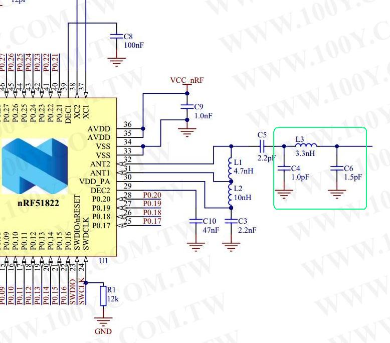
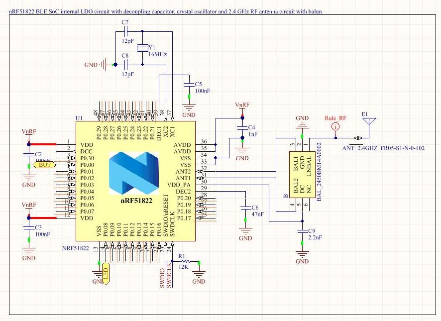
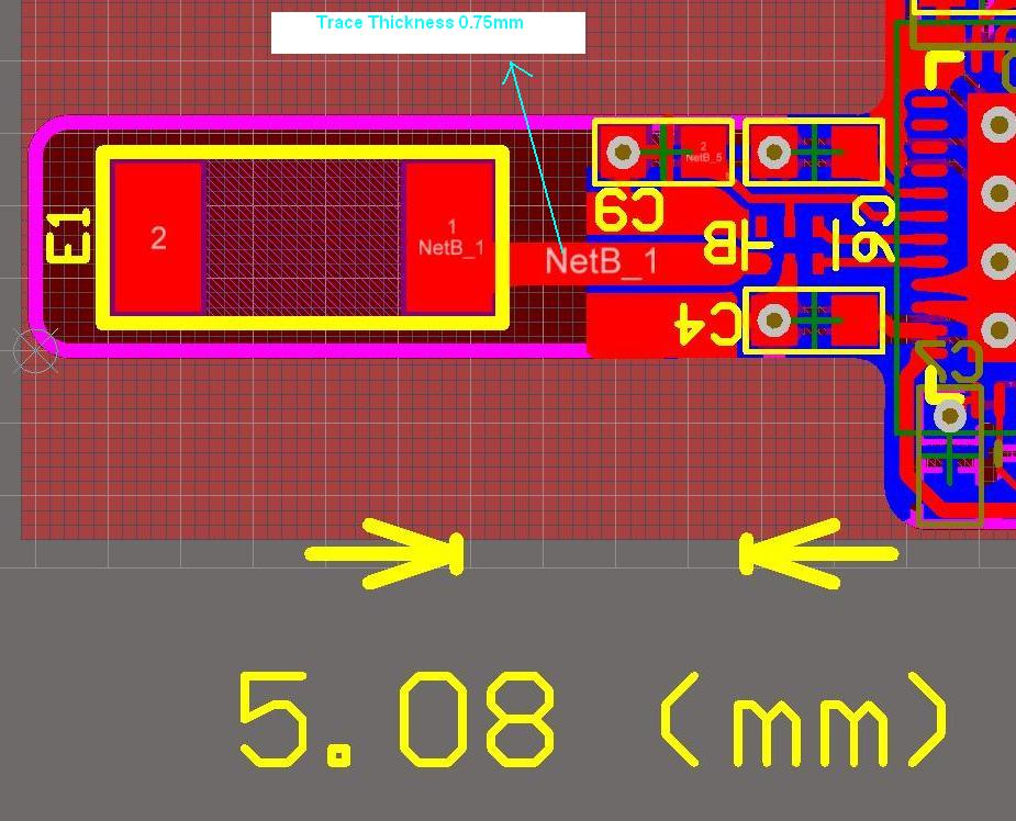
I used the nRF51822 Internal LDO Schematic Model. I have attached the Schematic and PCB RF trace picture.

Please advise me how to improve the range in such condition to achieve 150 Feet.

Looking forward your suggestion.

Regards.

Schematic_RF.JPG

PCB_RF.JPG

  • FormerMember
    0 FormerMember

    Hello,

    In RF Things work differently than in regular electronics due to the high frequencies, 2.4 GHz. If the system (chip and antenna) is not matched, there will be reflections in the transmission line, resulting in loss. The chip and antenna can be matched using a 50 Ohms Reference point; matching the chip to 50 Ohm and the antenna to 50 Ohm. Which components that are needed to match the chip and the antenna to 50 Ohm depends on the initial impedances. Therefore, in order for a balun to match the chip to 50 Ohm, the balun has to be designed specifcally for that chip. Since the Johanson balun is not designed for the nRF51822, it will not match the chip to 50 Ohm. That is why the balun BAL*F-NRF01D3 has to be used. The chip antenna is said to have impedance of 50 Ohm. This is however under the test conditions at the manufacturer. Since the antenna impedance depends on the environment, it will not be 50 Ohm when placed on your board. Therefore, an antenna matching network, a pi-network, is needed for tuning of the antenna to 50 Ohm. The pi-network should be placed between the balun and the antenna. By following the suggestions above, the range should normally increase significantly.

    If the space on the board is very limited, it is also possible to use the WLCSP package.

    Edit: There is a new balun from Johanson technology that can be used with the nRF51822/422 QFN variant, it can be found here.

    Regards, Kristin

  • Hi Kristin.

    Thanks for detail reply.

    I redesigned the PCB and did not use the Balun this time. I used the discrete components (L and C). With new PCB I am getting range around 5M to 7M though my expectation is at least 30M (LoS).

    I like to ask,

    • For the RF design based on Discrete components looks like have a PI Model itself (Please see the attached). So to tune Antenna an additional PI Network needed?

    • I am also planning to make another design using Johanson Balun and PI Model. Do you think, its possible to get 30M Range (LoS) with proper PI Values? Sorry that I can not use the real Balun BAL-NRF01D3 due to its LGA and I am not able to do the assembly.

    Yes, with WLCSP room can saved. But for assembly issue I need to stay with QFAA.

    Thanks in advance.

    Regards.

    PI Network.jpg

  • FormerMember
    0 FormerMember

    Hi Nazmus,

    Normally, the range should be better than 5-7m. When using discrete matching network (instead of balun), the layout of the components should be a copy of our reference layout (or as close to a copy as possible). The reason for this is that the placement and the distance between the components influence the impedance.

    Regarding the questions: 1) Yes, the antenna needs an additional pi-network. All the components in the reference layout are for matching the chip to 50 Ohm. And, yes, it is important to tune the antenna.

    2) It is very hard to say what range you can obtain using the Johansson balun. By using the Johansson balun, you don't know to which impedance the chip is matched, so even if the antenna is matched to 50 Ohm, there will still be a mistmatch between the chip and the antenna. It is better to use a discrete matching network, beacuse then both the chip and the antenna can be matched to 50 Ohm.

    Also note that in order to obtain a stable/non-sensitive antenna, the bottom ground layer should be as large and solid as possible, because ground is the reference for the antenna; the impedance of the antenna is 50 Ohm with respect to ground.

    Regards, Kristin

  • Hi Kristin.

    Thanks for all your valuable information.

    I achieved around 18M range LoS finally after tuning the discrete parts.

    Regards.

  • Hi All.

    Is the RF range performance is same for nRF51822 QFAA and CEAA packages?

    Actually, I am re-designing my PCB and need to meet smaller size hence chooses the CEAA. Just a bit confused ... with proper Antenna Tuning will I get similar range performance as QFAA?

    Thanks in advance.

    Regards.

Related