
Hi there,
I'm using the PPK (v1.1.0) to measure my nRF52 DK (v1.1.1). My sample programm is very simple: set up the LFXO, RTC with 8s CC-periode and the BSP_LEDs:
const nrf_drv_rtc_t rtc = NRF_DRV_RTC_INSTANCE(0);
static void rtc_handler(nrf_drv_rtc_int_type_t int_type)
{
  nrf_gpio_pin_toggle(BSP_LED_3);
  nrf_drv_rtc_cc_set(&rtc, 0, RTC0_PERIODE * 8, true);
  runFFT = true;
}

static void rtc_config(void)
{
  nrf_drv_rtc_config_t config = NRF_DRV_RTC_DEFAULT_CONFIG;
  config.prescaler = 4095;

  nrf_drv_rtc_init(&rtc, &config, rtc_handler);
  nrf_drv_rtc_cc_set(&rtc, 0, RTC0_PERIODE * 8, true);
  nrf_drv_rtc_enable(&rtc);

  // enable auto-reset of RTC0
  nrf_ppi_channel_t ppi_channel;
  nrf_drv_ppi_channel_alloc(&ppi_channel);
  nrf_drv_ppi_channel_assign(ppi_channel, (uint32_t)&NRF_RTC0->EVENTS_COMPARE[0], (uint32_t)&NRF_RTC0->TASKS_CLEAR);
  nrf_drv_ppi_channel_enable(ppi_channel);
}

static void FPU_enable(void)
{
  SCB->CPACR |= (3UL << 20) | (3UL << 22);
  __DSB();
  __ISB();
}

static void FPU_disable(void)
{
  SCB->CPACR = 0;
  __DSB();
  __ISB();
}


int main(void)
{
  NRF_CLOCK->LFCLKSRC = (CLOCK_LFCLKSRC_SRC_Xtal << CLOCK_LFCLKSRC_SRC_Pos);;
  nrf_drv_clock_init();
  nrf_drv_clock_lfclk_request(NULL);

  rtc_config();
  bsp_board_leds_init();
  bsp_board_led_on(BSP_BOARD_LED_0);

#ifdef FPU_INTERRUPT_MODE
  NVIC_SetPriority(FPU_IRQn, APP_IRQ_PRIORITY_LOWEST);
  NVIC_ClearPendingIRQ(FPU_IRQn);
  NVIC_EnableIRQ(FPU_IRQn);
#endif

  while (true)
  {
    if (runFFT)
	{
      nrf_power_dcdcen_set(true);
      FPU_enable();
      sine_freq = ((uint32_t)rand()) %((uint32_t)(SINE_WAVE_FREQ_MAX * FFT_TEST_SAMPLE_FREQ_HZ / 2.0f));
      testFFT_f32(sine_freq, 2048, false);
      FPU_disable();
      nrf_power_dcdcen_set(false);

	  runFFT = false;
    }

    __SEV();
    __WFE();
	__WFE();
  }
}
With two different Amperemeters (Agilent and Fluke), the sleep current is around 2.4uA (while performing the FFT 4.11mA), but the PPK using Otti v1.2.0 measures 13.9uA (FFT: 4.02mA).
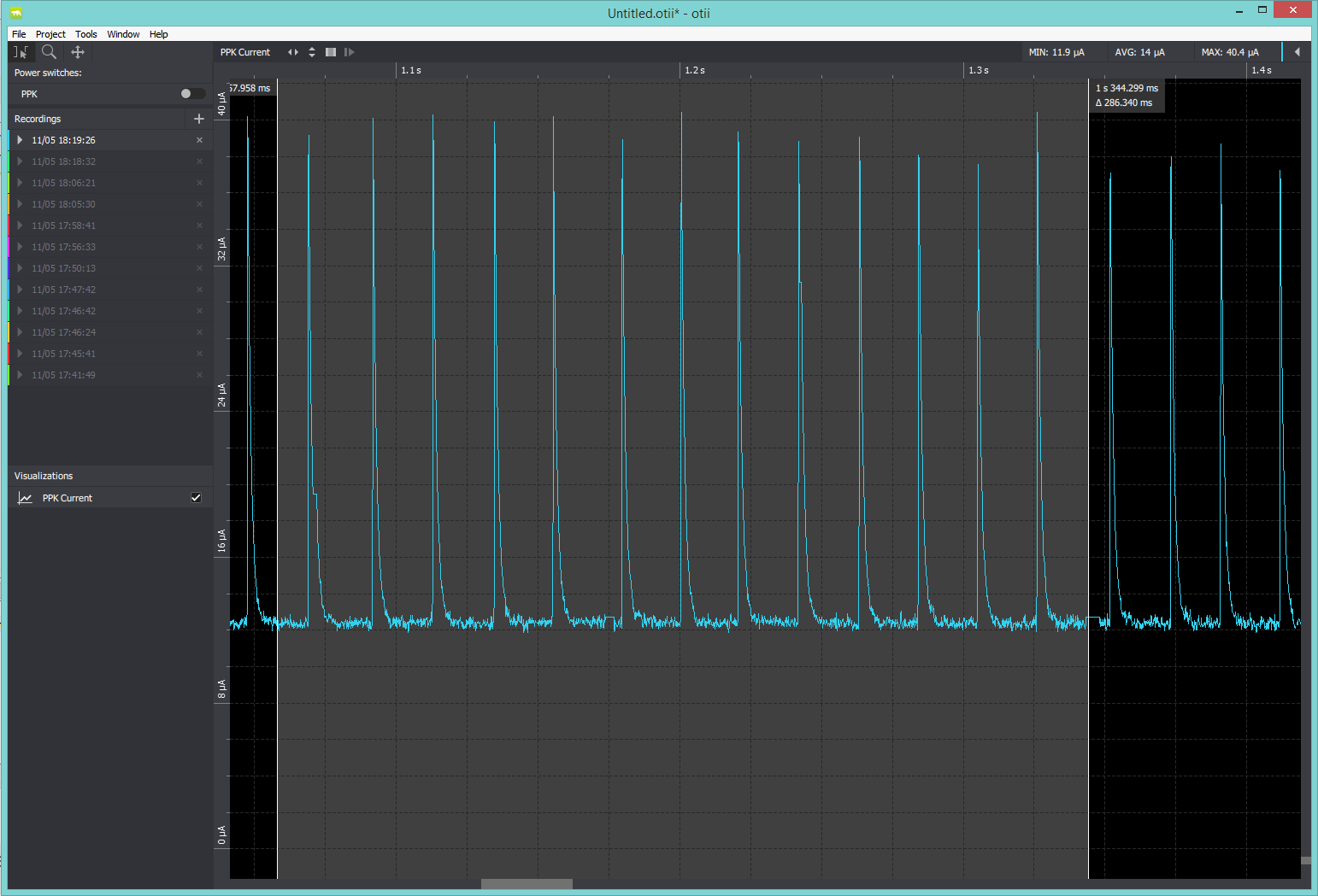
Is this in the range of measurement accuracy? The PPK manual states it's down to 0.2uA in the lowest range. Unfortunately I don't have an accurate µA-mA current sink to re-calibrate the PPK.
Do you have any ideas to improve my measurements and/or code optimizations?
Thanks in advance, Oliver
PS: Does anybody know, what causes the peaks in Otti? They are near to 45 Hz (our mains is at 50 Hz)?

